Sunday, 31 January 2016

Headlights & Indicators.

While I wait for the water pump to arrive I decided to get on with fitting the headlights and sidelights (now I have all the correct parts from S&J).


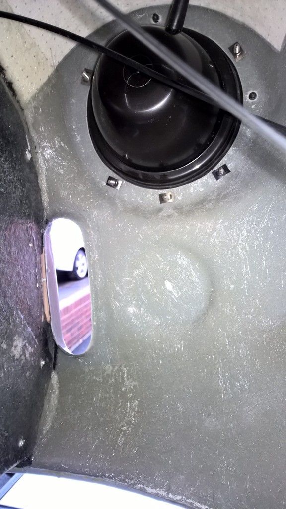
First make a template of the rubber seal on the headlights and drill the adjuster pin holes top and left. These need to be 8mm for the pins to fit through (start small and then open up the hole and don't forget safety mask as you're drilling fibre glass).

Remove the inner chrome mounting plate from the plastic bowl.

Next place the seal onto the plastic bowl and offer up into position. Drill at 3.5mm the fixing holes and then use No.10 self tapping 3/4" or 1" screws to fix it into position.

Push into place the small rubber grommet for the wiring to enter through inside the bowl. The wiring will be left for now and I'll come back to it when I do the main loom. 

Now attach the headlight to the inner chrome mounting plate, ensuring you have the correct orientation of the headlight so that when you put the mounting plate onto the bowl the headlight remains the correct way up. The headlight simply secures onto the mounting plate with three retaining clips. Loosening two of these and removing the third should be enough to fix in the light.

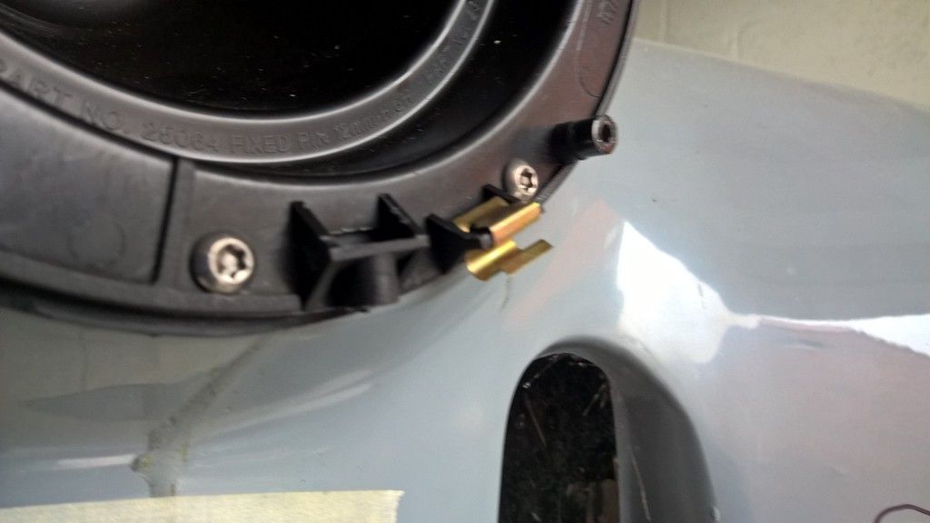
The mounting plate secures onto the bowl by hooking into place on the two adjuster pins and securing with the retaining screw.

Ensure you have a small retaining clip on the square flat plastic plate as shown in the picture. These were missing from mine when I received them and S&J had to send them separately.


Place the chrome outer ring into position ensuring it lines up with the retaining screw holes (just off centre bottom right) and that it is hooked over the two plastic rims top left and top right. Insert retaining screw.

NOTE: the other hole in the outer rim is a drain hole.

Onto the indicators.

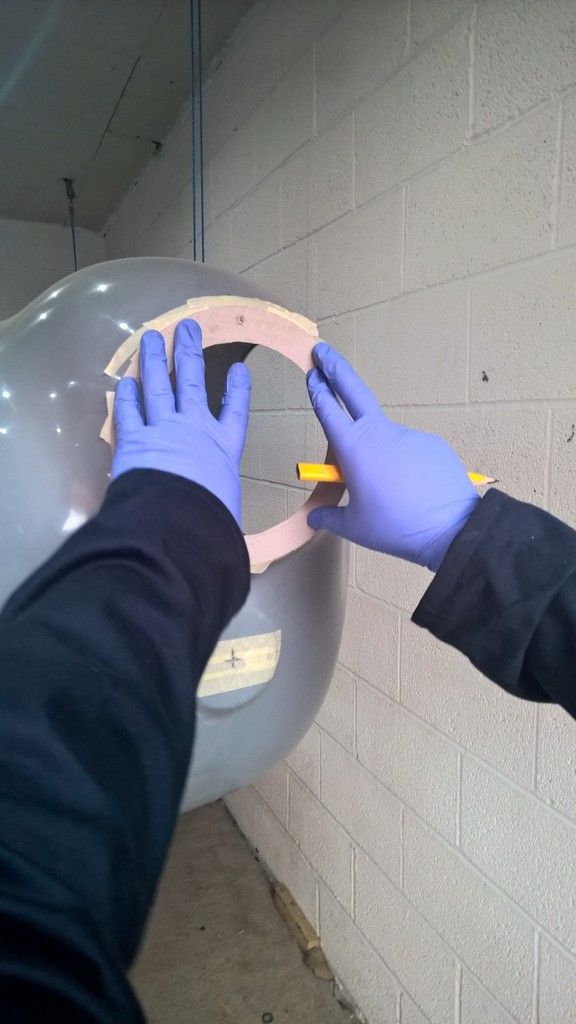
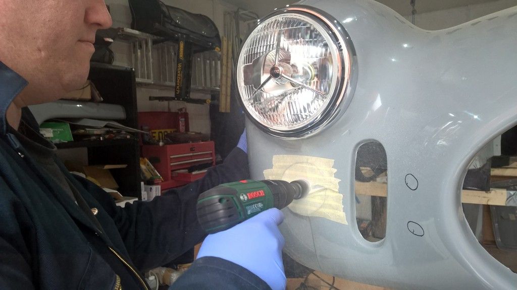
Locate the centre of the moulded area of the indicators. I measured this to be 4.25m radius.

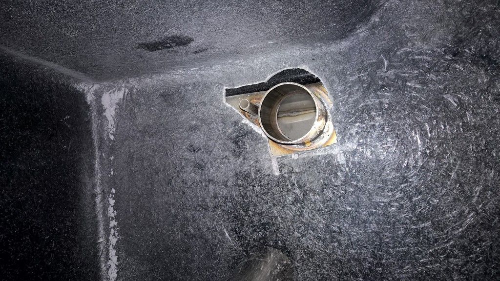
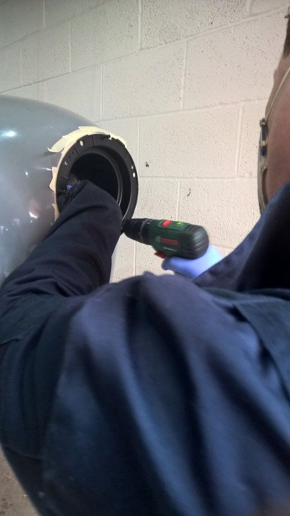
Drill a pilot hole at around 3-5mm and then use a circular cutter to open the hole wide enough to fit the light into position. 


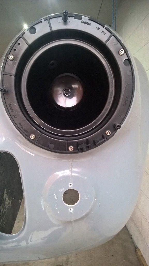
My lights attached with two 5mm bolts so an additional two holes were needed to  fit the light into position (other lights may vary). Simply place spring washers and bolts or a nyloc on the bolt to fix into position.


Then just repeat on the other side of the car.

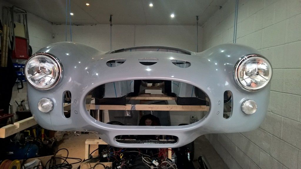
For the eagle eyed - you'll see me daughter who was helping "photo bombing" me. 

I'm pleased with the P700's and whilst I wait for the water pump I'll move onto the side repeaters next.


Water leak Update

Those that follow this blog regularly will know of the water leak from the recent posts.

Well, after waiting for the new gaskets to arrive, only to then have to order a new bolt I rebuilt it all and it leaked again!! 

Not straight away I'll add; it had to lure me into a false sense of security first. I ran it up to temperature and switched it off, let it cool for 20 minutes then ran it up to temperature again.

No problem.

The next day I went to do the same and within minutes it was leaking water. So another strip down required. 

I have traced the water flow and believe its coming from under the water pump pulley so a new pump is on order and it'll be 2-3 weeks before its here and the car can be run again.


Sunday, 24 January 2016

Head meet brick wall!

The Mrs was heading out with friends this weekend so the plan was to achieve loads of little jobs on the car. You can probably tell it didn't quite work out that way!

The new water gaskets had arrived so the first job was to refit the water pump and build up the engine coolant system so I could run it again. As I was mounting it I noticed that one of the bolts was much shorter than the others and only about 3 threads were entering the block - probably the cause of my issue in the first place.

So after kicking myself for not noticing this in the first place I drove around all the diy shops locally to source another and they were all closed. By this time I was fairly annoyed so I ordered another bolt from ebay and moved onto the next job.

Next up was to fit the power steering lines now that I had good access with the radiator header tank being removed. This job actually went really well and I'm pleased with the result. After connecting the main pipe with two M6 rivnuts and bolts I decided to follow its lines with the return pipe and cable ties. 


Next up was to drill and tap the holes for the water bottle. Time for the next issue.

As you can see from below the washer bottle is fouling on the air intake pipe whereas I have 15mm clearance on the radiator header tank. I've emailed AK in the hopes they will modify it for me as a welder is one thing I don't have.


So then I decided to look at painting the wheel arches with isoflex rubber. Unfortunately the tin said it will dry within weeks once opened and I didnt have time to do the whole job so that was out the window until another day.

Onto fitting the front indicators...but my verniers battery had gone flat so I couldn't measure up!

This was all on top of last weeks fitting of the P700 which went well until fitting the outer ring. After a call to S&J it turns out they hadnt given me some clips I needed so they are now in the post on their way to me. 

Weekends like these test your patience on these builds, but I'm sure once I have the parts and fire it up again it'll soon put a smile back on my face.

Time to go get a Sunday roast dinner and forget about it until next time.

Thursday, 14 January 2016

Oil Pressure Sender / Smiths Guages

When using the smiths flight gauges with the LS6 engine, the senders that are calibrated to the gauge are 1/8 NPT thread, which is significantly smaller than on the LS engine.

As a result I found myself taking parts off of another Cobra owners car at 10:30pm at night in order to do the first fire the next morning, but the fix is fairly simple.

carbuildersolutions sell all the parts required, which is essentially an M16 to 1/8 NPT adaptor and a 3 way 1/8 NPT T Piece (1 male, 2 female).

Why a 3 way?

Well, what the manual doesn't tell you is that the pressure sender gauge (or oil pressure transducer as smiths call it) does not operate the low oil pressure light, this requires a separate oil pressure switch. Luckily carbuildersolutions also do these.

Fitting is simple as the NPT threads just screw together and make a seal. The adapter on the block may need PTFE tape or thread seal (not thread lock) if it doesn't seal just upon tightening.

Here is a picture of the parts together (from left to right: M16 Adaptor, 1/8 NPT T-Piece, Oil Switch, Oil Transducer).


Friday, 8 January 2016

ITS ALIVE!!

YES - THATS RIGHT - ITS ALIVE!!!!

And I am so happy with the sound and that fact that it started on first attempt. Here's a video of the attempt.


As with anything Cobra build related it didn't go exactly to plan.

The smith gauges come with 1/8NPT senders which require adaptors for the LS Engine. So Simon Smith came to the rescue and loaned my his adapter from his LS3 engine on his Cobra. (Thanks Mate)

After the first run of the engine it didn't want to restart; soon tracked down to a weak earth from the engine block so I can fix that no problem.

The bigger issue is that after a few runs I started to leak water from behind the water pump which suggests a failed gasket. This means a complete strip down of the coolant system again to fix the issue and of course £27 in delivery from the US for £6 worth of replacement gaskets.

But even with these issues, it simply cannot take away the sense of achievement so far; what a milestone!

Onwards and upwards the build goes :-)

Monday, 4 January 2016

Prep for first fire

Well were through Christmas already folks and it has been good to have some downtime with the family, despite spending most of it with the man flu. The kids enjoyed Christmas day and the Mrs made my day by getting me a few Cobra parts including a stainless washer tank, exhaust escutcheons and stainless side vents. It's always good at Christmas but I don't think I've been that happy with my presents since being a kid.

As I thought about the next job on the build my biggest concern became knowing everything mechanically worked before fitting the body so I decided to build up a test rig that would get me to the point.


First job was to fit the Canems ECU, mainly because one of the sensor connections goes behind the starter motor. Finding the sensor locations was more difficult than I thought; being a first time builder its not immediately obvious where everything goes. I obtained the wiring diagram from Dave at Canems and then tracked down the images to the left and right on the net which helped to identify where to connect the ECU. I make it sound easy but actually this took a few attempts to get everything where it was supposed to be. 

The Canems ECU is very well made, with all the connectors plugging straight onto existing sensors. Canems can also provide the modified fly by wire pedal (which AK can incorporate onto their pedal box) and the air temp sensor (which is a standard GM resistance curve sensor on the LS).

Once the ECU was connected to the block I could fit the starter motor. A fairly straightforward job of putting in two bolts.

Next - onto some fabrication out of bits of wood I had around the garage. I wanted to create a panel to attach the clutch, brake servo and pedal box onto as well as a full scuttle hoop to be able to attach the steering column to. This job is very easy to do with a few angle brackets, 7-10mm drill bits and a few drill mounted hole saws (the same as you would use for the indicators). Some parts of the job require a couple of people and/or G-clamps to hold bits in place whilst its screwed together but in just a few hours you can have it put together.

To keep things simple I decided to ditch the AK loom for the test and create just the wires I needed to as troubleshooting would be much simpler if I knew what every wire did. 


First was the positive battery wire to the start motor, second the negative to the cut off switch which I then earthed to the passenger side chassis rail.

Then I had to figure out what wires on the BMW stalk were the ignition. Simply put its:
  • Thick Red - positive input from starter motor
  • Thick Green - First ignition click power out
  • Thick Purple - Second ignition click power out (connected to fuel pump relay for the test)
  • Black/Yellow - Momentary start power out (connected to small input on starter solenoid for the test
Next up was to fit a spacer that davidg from the cobra forum had made for me as the drive belt was going to foul on the thermostat housing. It required some M6 x 55mm flange bolts which I had ordered earlier in the week. 

Luckily I had another O ring from the previous thermostat to ensure it all sealed properly but if you didn't have that I am sure any water gasket sealant would work.

The workmanship from david was perfect and after filling with coolant not a single leak.

Last two jobs - power steering and fuel delivery.

The power steering hoses were purchased through Earls the same as my custom clutch hose. They were great costing £120, both 1m long including all the joints I needed:

  • M14 pressurised input on BMW rack
  • M16 for return on BMW rack
  • Open hose with jubilee for power steering return
  • 5/8ths power steering adapter for pump
The clearance on the power steering pump wasn't an issue, but I did have to install the pump after connecting the hose so I could ensure it was tight. 


Finally I put 5 litres of fuel into the tank and ran off a litre into a bowl to clear any crud out. Then I filled the pump with fuel to prime it (obviously removing hoses and reconnecting as necessary). Wiring the fuel pump was a simple case of:

  • a 30amp relay running positive from the battery to the pump.
  • a negative running from pump to earth
  • a negative running from relay to earth
  • a 12v positive running from ignition position 2 to relay. 
Turning the ignition key then set the pump flowing which I allowed to run for a few minutes to ensure all items would take the pressure, that there wasnt any leakage and that the return valve was sending excess fuel back to the tank. 

A quick connect and bleed of clutch and brakes and.....

Everything was good so all in all I was pretty chuffed with myself. :-) 

After filling the power steering fluid (I used Dexron III ATF/PS Fluid) I turned the key for the first time to start to ensure the starter motor would engage and again all good. A clean sheet of tests passed with no leakage or re-work required.

I have just the fan to connect to the Canems ECU and the oil pressure gauge to connect which I ordered today from Digital Speedos. Dave from Canems is booked for Friday 8th Jan to come to my home and help me start her up for the first time and properly map the ECU now that I have lamda sensors (previously only mapped on the dyno).

So watch this space readers - I expect to post a video of the engine running this weekend - a major milestone if I achieve it.


Sunday, 20 December 2015

Its nice to have a fan

Christmas preparations, a busy work life and low funds are slowing progress at the moment, as is waiting for key parts to move the build forward.

My drive belt should arrive this week and then I need a spacer for the thermostat housing as the LS6 housing when turned as AK do on the LS3 fouls on the drive belt. Once I have these I can plug in the ECU, connect to the pedal and start button and in theory it should all start up.... well see if that works out to be the case.

In the meantime I thought I would get on with another job that I realised I hadn't thought of - the radiator fan. A rather important oversight when doing the cooling system, which I had already filled with coolant. The air was a little blue when this dawned upon me.

I managed to source a trimline chromed 16" fan which another cobra had in their garage. This came recommended from a different cobra owner so hopefully it will do the job.

Then - first problem!

AK had fitted the air filter so close to the radiator that I couldn't offer up the fan properly so first job was to take of the air filter and stainless air intake pipe and cut 2cm of the pipe. A quick job but it felt like such a waste of good stainless steel - never mind, it had to be done.

Once offered up I realised that the great thing about a 16" fan is that it pretty much fits between the two AK radiator brackets which means you don't have to use the ugly plastic zip bolts that most radiators use. It took just a few minutes to locate and drill the top bracket and locate the bottom fan holes but then.... second problem... the bottom bracket didn't quite reach the bracket.


Light bulb moment - I had some 100mm Wickes angle brackets and the holes lined up perfectly so I trimmed the brackets down, painted them up and then put one M6 bolt down through the radiator bracket and angle bracket (same face as the rubber grommets) and the other M6 bolt through the bracket and radiator.

To help ensure the bolts don't bottom out on speed humps I trimmed the bolts down to just passed the end of the nyloc.

Another task completed and now just to await the last couple of parts before refilling the cooling system.


All that remains to say to the blog readers is for those that celebrate it, Merry Christmas and I wish you all a happy new year. I look forward to what 2016 brings the build.

Friday, 4 December 2015

Ancillaries and Shiny Bits

After cleaning up the water pump with the polishing kit I had a go at the alternator bracket. This polished much easier than pump and now it has a shine to it, not quite fully polished but good enough for me. This meant I could finally put the power steering pump and alternator onto the engine. 

First though I had to tackle another one of those minor cock-ups which was the brake flexi pipes at the front were catching on the wheels at full lock. It appears on the rear the flexis need to point downwards towards the chassis, wheras at the front they need to be upwards. The picture below shows the correct way (right of the pic) and how I had it (left of the pic).


Easily corrected and onto the slow task of fitting the power steering pump. This job was fairly straight forward but I had to present the pump up from underneath the car as the header tank was in the way. I said in my previous post but to re-iterate; you are much better off sorting all the engine parts before fitting the cooling system as it just gets in the way.

Before moving onto the alternator I decided to fit my edelbrock valve covers. These are designed to fit the coils too but in typical aftermarket style, the holes on the cover dont line up with the holes in the coils so I am going to use a coil relocation bracket instead. 


Also in true aftermarket style, despite it stating the covers are for LS1 & LS6, there is a note inside saying that the parts are designed to go on custom installations and may require modification. In the AK Cobras case this mean removing pretty much all of the front of the cover to shape it around the alternator mounting bracket. 


It also meant taking 15mm of each of the mounting lugs to move it closer to the valve cover and a small part removing to allow the breather pipe to pass through it. It requires M6 * 1, 35mm long cap screws to attach it.

The cover was a bit of a mess after I had finished cutting with the angle grinder but the file and polishing kit tidied it up nicely and I am very pleased with the result. 


It fits quite snug into the alternator on the pic but there is actually about 2-3mm gap between the two. 


I haven't completed the other side yet so that's the next task, along with measuring up for the serpentine grooved belt. 

I've also picked up the battery, a Yuasa 50ah from Halfords but I am waiting for the battery wire connectors to arrive before I can jury-rig something together to test fire the engine. Hopefully just after Christmas it'll make noise for the first time since it ran on the dyno in March 15.


New Thermostat

The new thermostat has arrived so I decided to get it fitted and fill the engine and radiator with coolant. This is because I had noticed some limescale-like flakes in the water pump housing and I figured it would be much better to get the water/coolant into the system to prevent any more occurring.


Before doing this I removed the water pump to clean it up a little. The aluminium polishing kit I had purchased from metalpolishingsupplies.co.uk did the job well and if I had a really small detail polishing wheel I could have done even better, but I am happy enough with it compared to how it was. 

Once the engine fires up and has been run to warm I'll drain the system and re-fill it just to make sure I've got rid of any junk from the engine.

I bought concentrated coolant from Halfords and mixed it at 3:1 (water:coolant) and the system still took about 4 litres of coolant to fill it.

For those following the blog regularly, you'll know I  don't have the heater yet so for now I have connected the two heater hoses together so that everything is sealed.

A learning point here is make sure you have all your engine accessories sorted before doing the cooling system. I have not yet finished fitting the alternator and power steering and I'm finding it very difficult to work behind the stainless header tank.


Sunday, 22 November 2015

Prop Me Up

Here comes a milestone moment in the build! 

First I wanted to say that when I started writing this blog I did it both as a record of my build and as a guide to others following in my steps. I received a nice email from a reader recently letting me know they enjoyed the blog which was highly motivational for continuing so I just wanted to say thanks to all the people who come and read my articles. 

I have now installed the prop shaft which means the drive train from front to back is connected. The car could, if the engine started yet move under its own power.

Alas we are some way of that milestone; I was hoping for Christmas but I now think it could be Feb when the its alive.

Fitting the prop shaft was fairly straight forward with the body off as I had lots of room to do it. 

1) After applying a small amount of copper grease to the slide yoke splines I inserted that end into the gearbox with the rest of the prop shaft below the differential nose. 
2) Insert further than it needs to go so that the flange end can be "carefully" manoeuvred onto the differential nose shaft.

Now to avoid the short interlude in the process that I went through whilst going to the hardware shop it will be helpful if you have 3 M12 * 50mm bolts with 2 washers on each and a M12 Nyloc for each. I had 35mm bolts which were not long enough. I am assuming here that you have a 3 hole diff nose.

3) I found it useful to slot the bolts through the prop flange before sliding it fully onto the diff nose as there are very specific positions where the bolts fit through. Some gentle tapping with a small tap hammer was required in my case. 

4) Tighten the bolts flush (not tight) and then go around each again fully tightening. I needed two 19mm spanners for this as I could not fit a socket on the bolt head.

Don't forget to ensure your prop shaft UJ's are fully greased.


Contrary to what the picture looks like, I have good clearance to all parts; I was especially pleased that my fuel pump bracket and pipes have plenty of clearance given that this was a bit of a gamble.

Once this was on I could move to filling the gearbox with fluid. The Tremec T56 Magnum recommended oil is Dexron III grade Automatic Transmission Fluid (at time of writing). Please check the tremec website for the latest recommendation. 

The fill point on a gearbox is on the side so unless you have bought a oil pump designed to do the job (Sealey 1L Litre Mini Pump For Engine/Brake/Gearbox Oil/Fluid/Cleaner TP6804) or you already have a funnel you'll need to do what I did and have a Blue Peter moment.

Basically just fill it until it comes out of the holes and then screw in the plug.

Pictured left is the device I made using a water bottle, duct tape and a bit of left over fuel hose after completing my fuel line (Pictured Right)

I have just used a Torques jubilee clip fitting for now but I am unsure if this is strong enough so I may change this in the future. I've sent an email to AK asking what they do before I decide.

I'll be fitting the side-pipes later just to keep them safe and then I need to strip the parts off the car to polish them up.

Like I said, a few jobs to keep me busy.

Finally - I also realised that the BMW Streering rack has a small black plastic cap on it. I have confirmed with AK that you just pull this off and dispose of it. This is pictured below:


Undo the hardwork

One of the frustrating things about building a kit car of this complexity is that amount of times you have to fit something just to take it off again later.

For example, the car looked great when it came back from AK but due to the amount of work still needed on the engine bay I had to take the exhausts back off, get the friends around to remove the body and hoist that back up to a working height and then start disconnecting the great pipework Jon at AK had done in order to fit the thermostat and polish/clean up the aluminium housing. 

I still have the polish to do and I've also order a new thermostat from ebay (US) as the delivery was much cheaper than from GM Parts Direct. This was only 40$ and I did already have one but it didnt seem to be working well and so I thought "better safe than sorry". 

Note: You can no longer buy the thermostat on its own, you get the housing with it as part of a single unit. 

The pedal box had to come back out as did the clutch and brake master cylinders.

In hindsight, I should have removed the stainless cover and then bought and fitted:

1) The heater box
2) The side vents
3) The front vent wire mesh
4) The triple nose vents
5) The brake and clutch Servo
6) Ensure all engine/gearbox work was complete

All before sending to AK as that would have saved me a load of re-work. Hopefully the readers of this blog can learn from this.

One thing I did do is mark out with tape about an inch above where the bell housing goes so when I fit the heater I can ensure I have the correct clearance.


The research on the heater system continues but there are a couple of other jobs I can do in the meantime. 

Tuesday, 3 November 2015

Its back from AK already

When the Cob went to AK I didn't expect to see it again for a few weeks given how busy they are so I was surprised when halfway through my holiday I received an email saying the car was ready for collection.


First, I promised to provide feedback on grim salvage who took the car to AK. They were excellent, arriving bang on time, taking their time to ensure it was loaded carefully and secure including using extending ramps due to the car being so low. The driver was friendly and it was well priced as I mentioned before.

I even received a text from them to say the car had arrived at AK safe and sound. 

Whilst on holiday in Turkey, I sent them a text to try to arrange for them to pick up the car and they were flexible enough to say yes at short notice, without paying any deposit, arranging all over text. 

Having arrived back home in the UK at 4am on the Monday it was 9.30 before I text them to check all was ok and they were nearly at AK and had the car with me by 2pm for cash on arrival.

I can't recommend these guys highly enough.

Jon at AK had also gone beyond what I had expected, not just making a tidy job of the stainless headers and sidepipes (which look great), but fitting all the water pipes which I had purchased, including the air intake and filter. I am very happy with results and this now puts me in a good position to crack on with the build.

The AK team had even sorted my accelerator pedal out so it no longer rubs on the body which saved me another job. 


So now I have a wiring loom, lights, locks and door catches which I could fit but I want to get to starting the engine for the first time. For that I need the heater, battery, battery cable, switches and gauges to be able to properly fire things up safely.


To sort the heater ill need to decide on which way to go as I'm still not sure about using the standard AK option.

More research is now needed.


Sunday, 18 October 2015

Exhaust preparation / Transporting your precious project

This week has been a little quiet on the Cobra front as its off to AK on Thursday for the stainless headers and sidepipes making. I went a bit "bright eyed" on the order and added the cooling pipes, stainless header tank, air intake pipe and filter as well as the wiring loom. The card was already preparing itself for a £4.5K hit...ouch...

All I had to do was bolt the body down and arrange for it to go, then go on holiday and hope it was ready when I came back.

This time my mechanic friend was on holiday so couldn't transport the car. "No problem" I thought  "AK can do it".

A phone call later and I realise their normal driver charges (at time of writing) £1.25 per mile which worked out at £255 each way!! an expensive addition to an already expensive order at AK. I needed another solution.

A quick Google search later and I come across AnyVan.Com. This is a simple site where you put where the car is going from and to and then companies can "bid" for your job. It started at £150 but within 20 minutes it was down to £123, less than half the price of the AK driver. The company I went with is based in Ripley, West Yorkshire 

Email: grimsalvage@hotmail.com

Once the pickup occurs I'll let readers know how it went.

So back to the prep,

I was worried about the car getting damaged during transport so decided to hook up the brakes and steering column so the car was a little safer to manoeuvre. 

Everything has only been loosely fitted and will be removed later. One tip I have here is take the collapsible part of the column out and feed that through the hole in the bulkhead first, attach it to the AK provided steering rack extension (the black bar with 2 UJs) and then get someone to hold this still whilst slotting the column back onto it.   


Another tip is pre-fit your brake pipes to the Servo and have connectors down near the chassis otherwise it is extremely difficult to connect them together.

Katie came out with Monroe to help bleed the brakes which took us a while as there was an air lock that just wouldn't clear. I finally managed to clear this just as I ran out of brake fluid to top up the reservoir.  

All ready to go. The next time I post I'll have some side pipes :-)


Sunday, 11 October 2015

Body first fit

The Cob is heading down to AK at the end of the month for the exhausts making so I needed to get the body back on the car.

First I painted the inner wings with black high temp POR-15 that I had left over from the donor parts. This was to ensure that the stainless cladding had a better reflection once the film was removed. I couldn't think of anything worse than seeing the grey fibre glass in it.

Then final prep jobs.

First to remove the T56 gear shifter and cover the hole to ensure nothing gets in the gearbox. Easily done (six bolts and just pulls off). I wanted to do this so I could decide where to locate the shifter at a later date.

Next; ensure fuel, clutch and brake lines are out of the way. Enough said on this.

Finally cut holes for fuel filler ....... Worry time!!!

This is the first time I have cut a hole in the body and getting this wrong would be a disaster, both for the car and my confidence going forward. My brother was on hand today to ensure I had two minds on the job; so measure 20 times and cut once then hope all was ok. We decided to go with a hole that was just large enough with the plan to open up the hole later.

Next up was to attached the pedal box and servo so that brakes could be connected to help manoeuvre the car on and off the trailer at AK. I decided not to peel off the protective film from the stainless cladding as the body was going to come back off later for the heater fitting so I figured I just remove the servo at that time.

Here I noticed a bit of a problem in that the accelerator pedal was catching on the body. As this was a custom pedal box by AK (as its a canems ECU - fly by wire) I decided to leave this until I can show AK and get their thoughts.

And now time for the fitting which is a 2 minute job once you have managed to round up 4 of your friends to help lift. A few beer bribes and I soon had the lads around and on it went.


The hole for the filler did need a little adjustment but not much - luckily.


I'll bolt up the body later but for now I have something that is starting to resemble a car


.


Saturday, 3 October 2015

Rolling chassing complete .... I think!

How time flies when you nip into the garage to do a couple of jobs on the Cob....

The Mrs was out tonight so I headed into the garage to try to complete the rolling chassis; on todays list was:

1) Take the engine out again to figure out why the gearbox was leaning
2) Check I had used both a spring washer and washer on the P-clips as I had read on the forum IVA man was keen on this.
3) Connect the handbrake assembly
4) Fit the radiator

This would get me to the point where I could lower the car onto its wheels and prove it moved!

After taking the engine out I realised that I had not put a washer after the spring washer on each of my p-clips. The p-clips were metal not plastic so I figured I would be ok, but after re-thinking I came to the decision that putting them on now would save a LOT of hassle later if IVA man decided they were necessary. About an hour or so later and this was all sorted.

Before removing the engine my old man and I had taken a few measurements and almost come to the conclusion that the gearbox was supposed to lean slightly and that it wasn't 5mm out (see last post). Once we put the engine on the floor and noticed the engine was leaning 1 degree and the gearbox 4 degrees this confirmed it. If the gearbox was mounted correctly to the bell housing and the bell housing to the engine then it couldn't be wrong.... could it?

We agreed that it was all ok and set about re-installing the engine and fitting the gearbox bracket. (EDIT: It was later confirmed by Roadcraft that the GM Bell housings do angle the T56 gearbox)

After checking the height of the output was in line with the output on the diff (it only took 7 washers on the bracket!) then this was job done and onto the Handbrake.

First of all I would point out that the AK manual says sweet FA about the fitting of the level which makes the handbrake work. Luckily there are some pictures on various blogs which help. The two cables need to be adjusted to different lengths to get them to work at the same level so don't be afraid to play with them to get it right. My drivers side cable only has about 1cm of the threaded bar after the nut and the passenger side about 3cm. The level does not require much force to lock both wheels solid.

I didn't have any clevis pins as per the AK picture so I used M8 bolts and nylocs to connect the mechanism together. Now onto the radiator.

AK supply a couple of small M6 bolts which are perfect for the top of the radiator along with a washer before and after the bracket. They also supply two M12 bolts for the top frame and 4 M8 for the bottom. You do need to get your own radiator rubber bushes from Rimmerbros though (£1.30 each). See a previous post for the adjustments I had to make to fit this.

Finally I lowered it to the ground. This was such a great feeling. Almost a month after receiving the chassis I was able to push it in and out of the garage and see everything working as expected. I'll need to order the prop shaft next and I have booked it into AK to have the manifolds and side pipes made at the end of October.