Sunday 17 April 2016

Roll bar brackets

As I had an hour to work on the car today I decided to fit the brackets for the roll bars, which also involves drilling the holes for the seat belt eye bolts. 

This brackets themselves are one of the most straight forward jobs there is, simple M8 bolts with spring and normal washers is enough to lock them down but it does take time as there is lots of off/on as you figure out the correct positioning for the eye bolt.


There was two holes in my body where AK had drilled the holes to pre-fit the roll bars and I found the eye bolts to be roughly 5 3/4 inches from this hole, about 3.75cm from the back wall lip. (apologies for the change from imperial to metric - I do that sometimes)

Frankly is a bit of trial and error but dont worry too much as you can easily fix a mistake with some P-40 (I'll certainly be doing this)

Many people complain about vibration in the roll hoops so I have fitted some silent coat to the underside of the brackets as removing vibration is one of its key features. 

For the bracket that is pre-fitted to the chassis I'll need to cut a circular piece and place it into the bottom of the bracket. This should significantly reduce vibration.


As this job went quite well I decided to place the roll bars into position. 

You can see from the photo that one went in easily, however the other is going to required some man handling to get into place so I decided to call it a day and I'll come back to this job later.

Looking back as I close the garage its a major motivation seeing a car instead of a rolling chassis; it really feels like I getting somewhere with it now. 

Hopefully I'll be able to get some time in the garage over the coming weeks to fit the rest of the lights, locks and latches as the windscreen is being collected at stoneleigh.


Saturday 16 April 2016

Body Goes On

At long last another major milestone was reached today when the body went on the car permanently but before I show the final result there was a couple more things to sort out.

First job was to fit the pedal box and servo and in true Cobra style this is where I hit the first problem. 

The accelerator pedal was catching on the body which felt like a disaster; I just couldn't bear the thought of that sticking whilst driving so after trying to push and pull it around, grinding a bit of the pedal and taking in and out what felt like 100 times, I came up with the idea of drilling out the bolt holes on the pedal box to 12mm. 

This allowed the pedal box to be moved 2mm further away from the side of the body which cured the problem but this job took hours to complete and frankly is one I am glad is over and done with.

I'm still not sure the adjustment on the clutch pedal is quite right but I can test that later once I've re-hooked up all the clutch and brake lines.

Next job was to prepare the chassis to accept the body. Normally this would involve putting silicone sealant all over the body. My view on this is its messy and unecessary as it makes it extremely difficult to ever remove the body, if the need arises. 

After some research I found an alternative which had a number of advantages. A product called silentcoat. I bought a bulk pack for £84.99 but I have loads remaining so a smaller pack would no doubt be ok. I spoke to the firm and they advised that as long as all gaps are filled by placing the pieces close together it would form a barrier. 


The product also reduces vibration, deadens sound and acts as a thermal barrier so I figured this would help reduce road noise so that I get the full engine/exhaust noise and help hide the whine from the fuel pump. it cuts to shape easily with scissors and follows the contours of the car well too as its only 2-3mm thick.

I even placed some in the tunnel so I'm hoping this works out well, mainly as it was a lot more expensive that silicon sealant :-)

It was finally time so a quick text to call round a few friends and on it went. I was surprised how quick and easy it went into place until I tried to put in the chassis bolts. 

There is two 8mm bolts that go right through the chassis in the boot and four M10 bolts through the wings in the engine bay. These all went straight into place. 

The main body was a little more difficult. First, the diagram in the manual shows that there is a hole at the front of the footwell but there isnt. There is five holes around where the driver and passenger sits. Two 10mm by the main scuttle that go right through the chassis - these would line up and took a while to locate.

The remainder are all 10mm threaded holes and again some were difficult to locate, others damaged the fibre glass as they slowly pulled tight. Not a major issue, just a little annoying.


AC Heater Unit - Part 2

The heater unit fitting needed to continue before the body could go on but there wasnt a great deal I could do on this. 

First I cut two holes in the stainless inside the area where the heater was going, one on each side of the tunnel. This was so that I could add footwell vents purchased from T7 designs. These just clip into place after cutting the right size hole (about 74mm).

Next was to drill holes for the water and a/c hoses to fit through. This is a slow and steady job, first use a 3mm carbide drill bit at slow speed with cutting fluid and after this you can open the hole fairly easily 2mm at a time with normal drill bits. Dont forget to use rubber grommets to protect the tubes.

A drain hole was also required to pass the drain tube through, but other than that all the edges were sealed with sikaflex to meet the IVA requirement that no air can be taken from the engine bay (note there is a caveat that drain holes are ok as long as they are less than 1% of the overall space used to take in air).

Following riveting the panel in place and adding a p-clip for the drain hose the stainless protective sheet was removed from the engine bay and now the heater will be left alone until after the body is on. 


Sunday 10 April 2016

Last few jobs before body

The heater unit still needs to be completed which I hope to do tomorrow, however, in the meantime I have managed to wrap up a few smaller jobs that needed doing ready for the body fitting. 

First up was to fit two p-clips to the fuel lines where they pass by the rear suspension arm. This was mainly to guarantee they didn't foul on the arm, which would be an IVA fail. The hardest bit of this job was drilling laid on my back under the car, it took over an hour to do just this job.


Next was to mark out and cut the hole for the fuel filler pipe to fit through, a fairly straight forward task that took just a few minutes with the angle grinder. 


Finally, it was time to cut the hole for the gear selector to fit through, This is one of the tasks I have been worried about because its easy to measure up wrong and until the body is on I wouldn't know if I had chosen the right gear select position (The T56 has to choices of selector position about two inches apart - I had it on the default rear select position)

To work out where the hole needed to be I marked on a piece of wood where the bolt holes where on the chassis and a mid point between these two holes. I then measured forward to the selector. Marking on the wood allows the wood to be held in position on the body giving a solid surface to measure forward down the tunnel to put a mark on the tape.

Next I measured the width of the tunnel, and the width of the chassis to calculate that I needed to be 10.5 cm across from the passenger side of the tunnel. 2 mins later I had a 3mm pilot hole.


I chose to use a large hole cutter to ensure I had enough room to bolt on the gear lever; I could have chosen a smaller one in case I had got the measurements wrong but I thought "lets live dangerously" - hopefully I wont regret that decision later!

So all that's left before the body goes on is a trial fit to test the extended heater tunnel, fit the heater, pedal box and servo and then I'm ready to go - I think.

Exciting times :-) 

Sunday 3 April 2016

AC Heater Unit - Part 1

From an early stage of the build I always wanted a useful heater / cooler because, like goldilocks I like to be just the right temperature.

This meant having the controls on the dash so this meant that they needed classic design. I also wanted modern controls, variable heat and dash/windscreen adjustment.

So after hours and hours of research I came to the conclusion that I wanted the controls made by old air products show below.

Unfortunately the heater unit was too big to fit in the car so I needed a separate unit. After more research and lots of checks to ensure I could connect these controls I decided to purchase the following unit from T7 Designs.

But I still had an issue. The T7 unit was compact, also did A/C (for when the hard top is on) but didn't allow for variable adjustment on water flow and dash/windscreen position. This meant I had to go back to old air products. Luckily they provide an "upgrade" for their units which has these options. Picture below.


How to connect the three parts together?

First I needed to know how much room I had and when I offered the unit up into position it became clear the unit would have to mount sideways. This actually worked out well because this meant the unit would suck air in from the inside of the car rather than the engine bay which is an IVA fail.

I also bought some stainless steel to extend the tunnel and box in the heater, also to ensure it wasn't pulling air from in the engine bay.

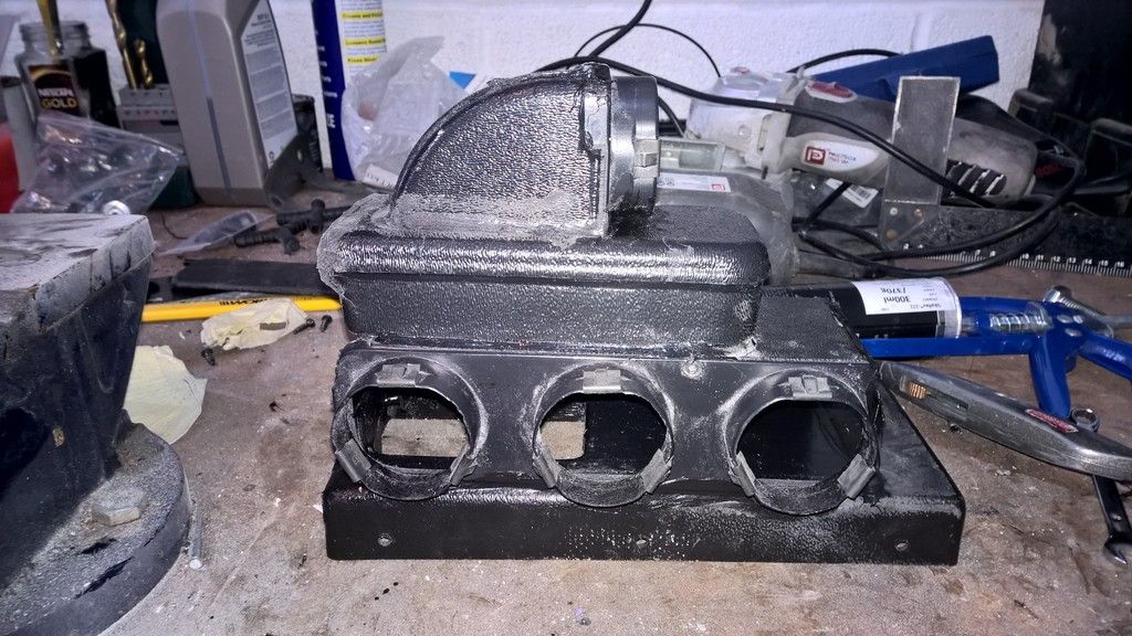
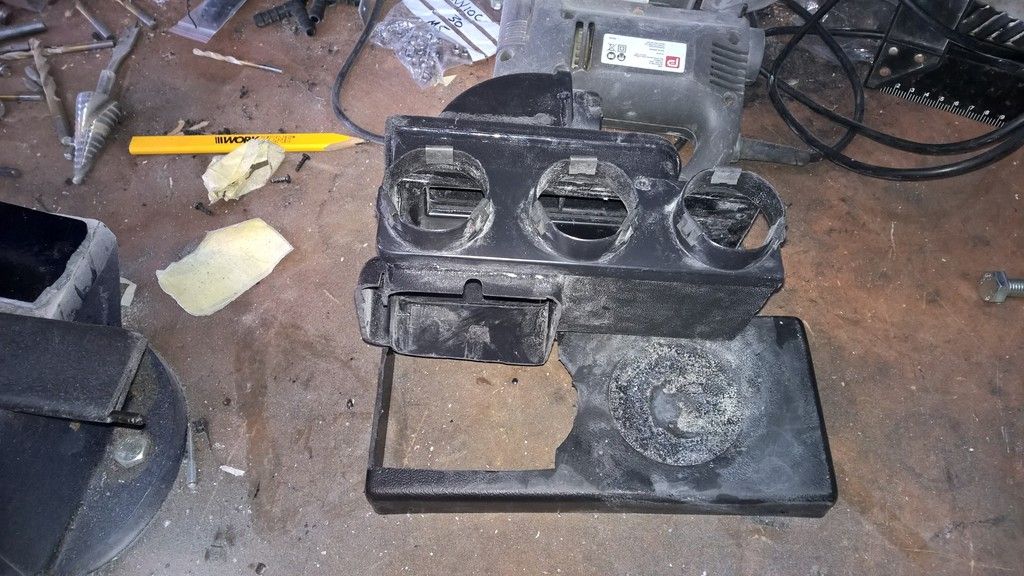
After making a wooden template I realised that the plenum from Old Air wouldn't fit as it came and so adjustment was going to be required. Nothing that some time with the angle grinder wouldn't fix :-)


Sikaflex was used to fix the parts back together and to fix the plenum to the front of the T7 heater casing. 

I'll come to the electrics later.

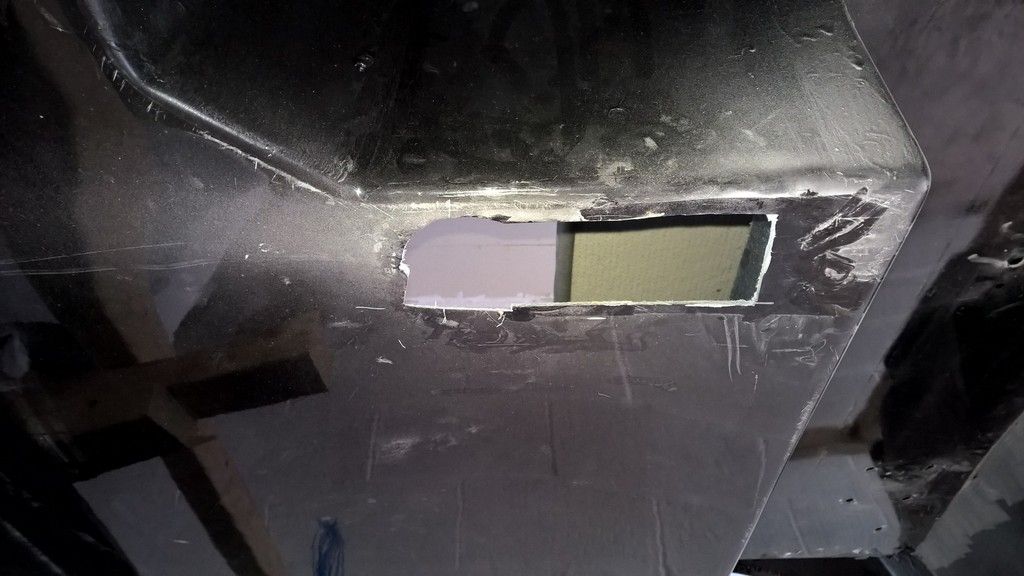
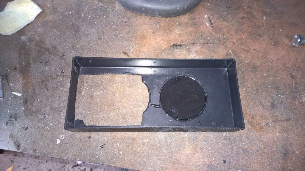
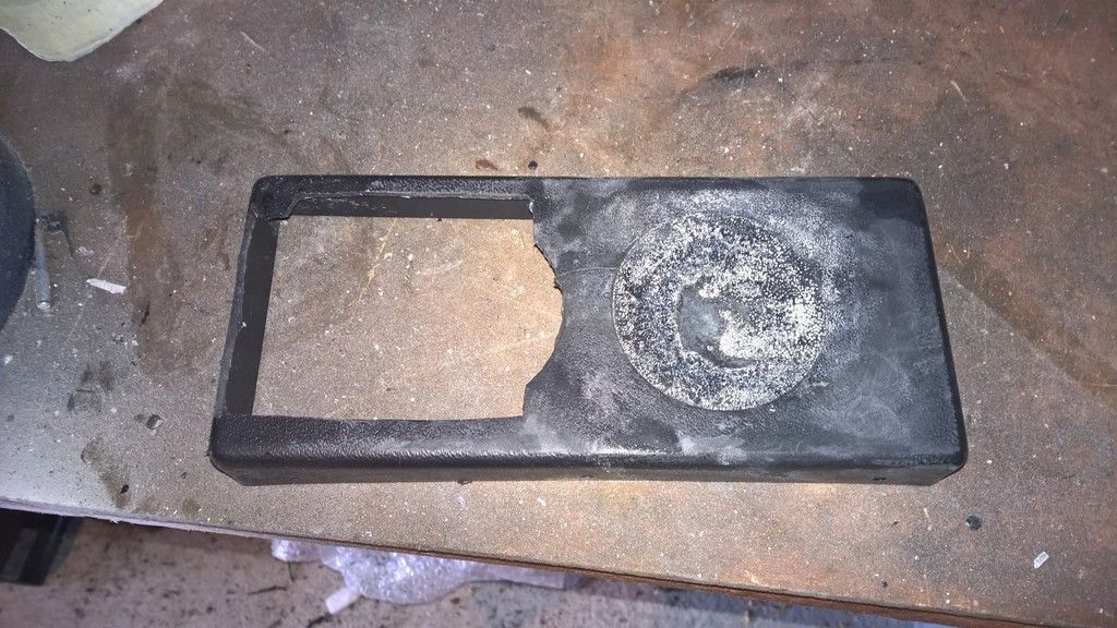
Before fitting the plenum to the heater casing I had to remove the two round connectors on the casing and then adjust it to fit the plenum. This involved cutting one side of the casing larger and blocking the other side up with liquid plastic, purchased from ebay.


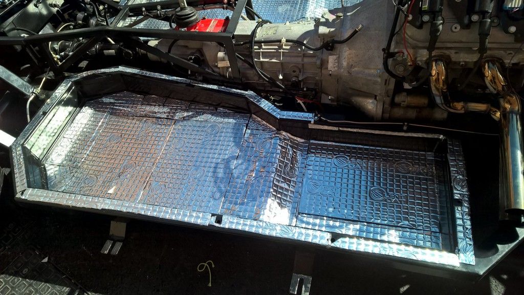
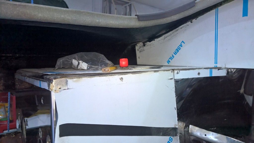
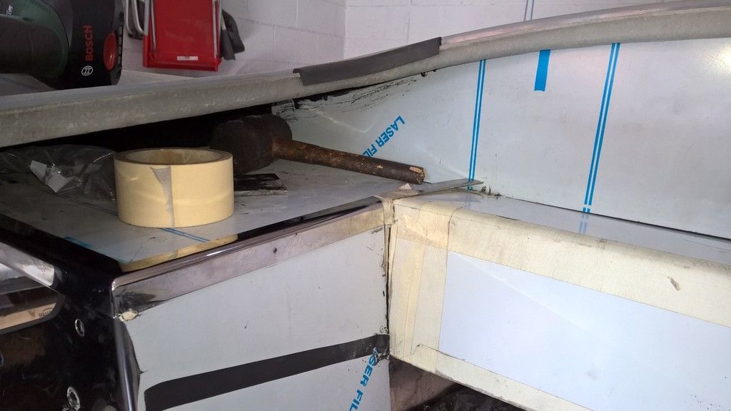
Before I could actually fit the heater unit I needed to finish making the stainless box in the tunnel. This meant drilling the steel to fit the shelf.

Stainless steel is HARD to cut, HARD to bend and HARD to drill but eventually I had the first piece in place allowing the unit to be offered up, connecting the drain pipe and air pipes. 

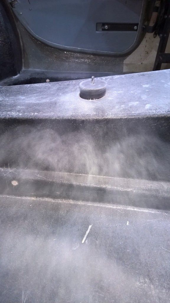
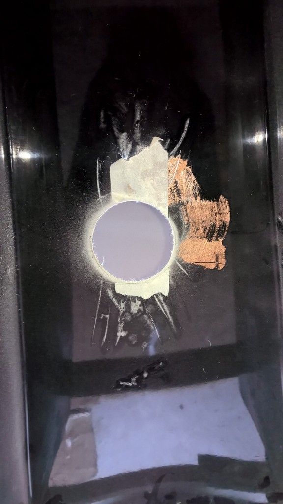
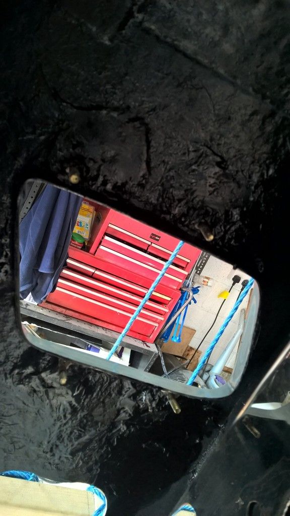
In order to ensure everything fitted I needed to cut a larger than normal hole in the body.


Then, I had to remove the stainless edgine strips AK had added in the engine bay. This is simple enough, just dill through the rivet head with a 3mm cobalt drill bit and then follow through with a 3.5 or 4mm bit to remove the rivet. 


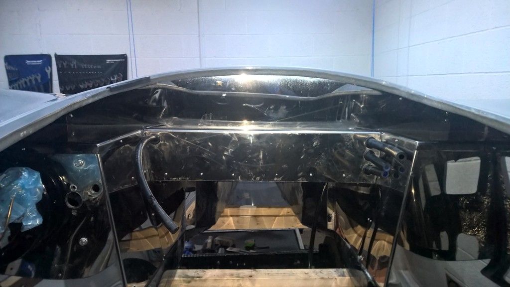
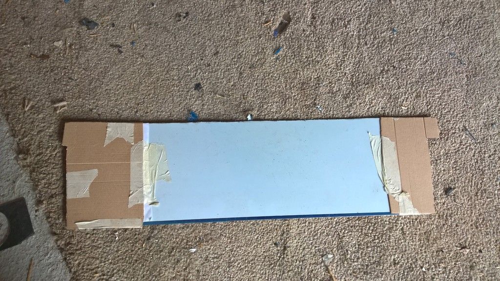
Next I needed to make a template for the front of the heater. I did this with a piece of steel and some cardboard. 


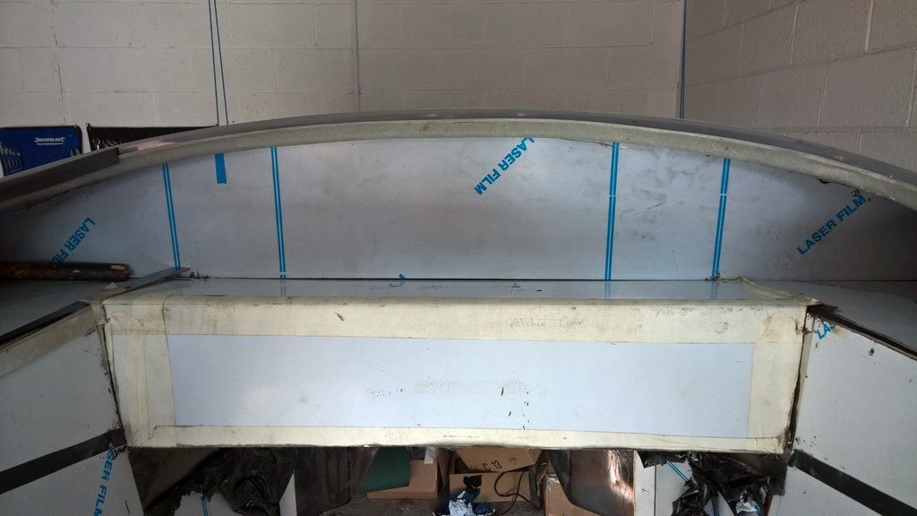
Thanks to Andrew Sharples for letting me borrow his sheet metal bender. The sheet measurements was 13cm for the top and then 16cm down for the front face. 11cm is the actual top, whereas 3cm slides under the front bulkhead like so.


Then I needed to trim the edging strips AK provided as shown below. 


Theres lots more to do on this. Watch out for part 2 coming soon. 
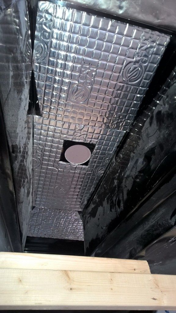
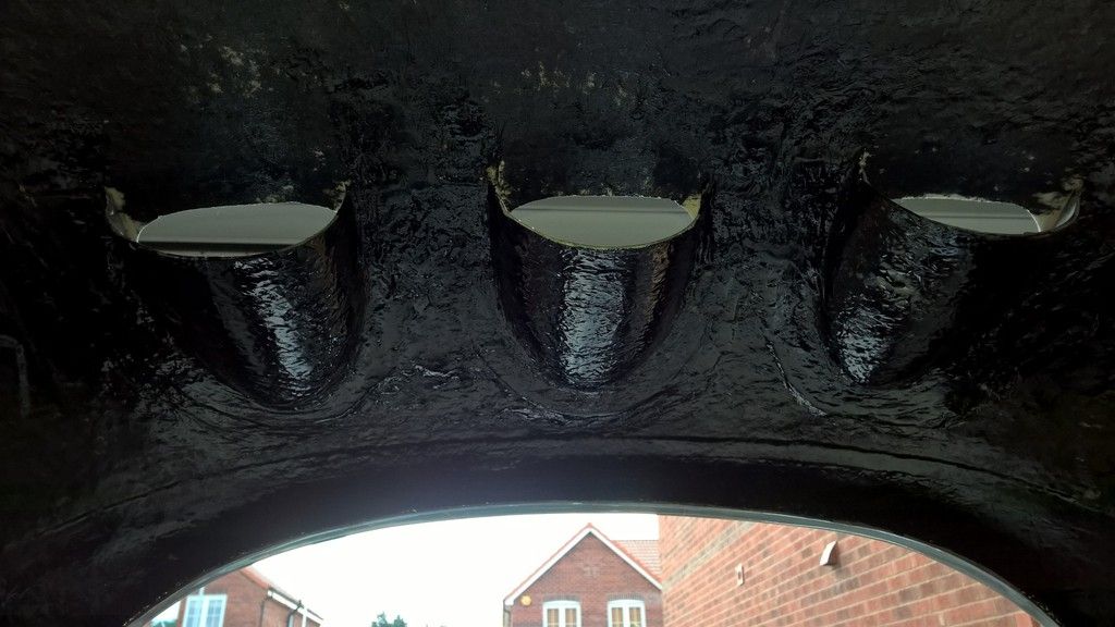
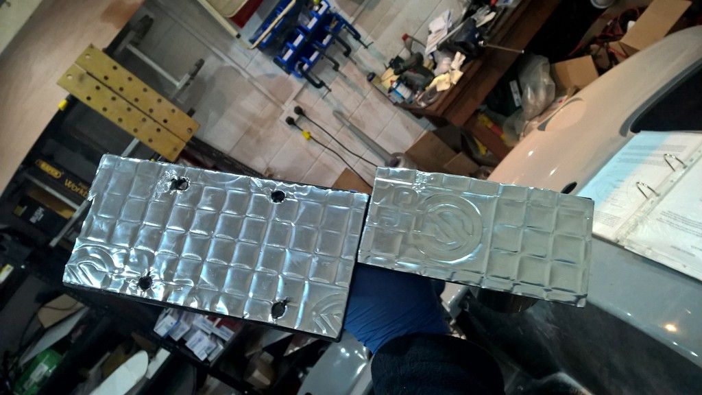
Side Louvres

Fitting the side louvres is fairly straight forward. I didn't like the AK option of fitting wood to the wing so I decided to buy some "big head" 6mm bolts which could be attached to the wing with P40, then the louvre bolted to that with a nyloc nut.

I first drilled four holes in the louvre and attached the big head bolts. They were a bit too big and needed trimming with the trusty angle grinder. The main reason for doing this first was to ensure the holes were in the right place once the bolts were glassed into the wing.

Before actually glassing them I removed the stainless steel sheet from behind where the servo goes as I imaged this would be more difficult once the louvre was in place.


I used a little P38 to attach the bolts to the wing still attached to the louvre (with washers holding the louvre away from the bolt head so I didn't accidently attach it in too). Then I glassed the bolt in by adding a dollop of P40 once it had dried enough to remove the louvre.

Standing and holding it in place until it sets takes the most time; about 10 - 15 minutes for each side.

(note to self - get a coffee prepared for the other side)

Repeat the other side.

A quick sand and touch up with POR-15 to match the rest of the engine bay and it was all complete.

Job done.


Triple Nose Vents

Fitting the triple nose vents is needs doing before paint if you are going the fibre glass route rather than alloy.

I chose this fibre glass as I want them painted the same colour as the car - the alloy just wouldn't have looked right with the colour I have chosen.

Fitting them requires a fair bit of standing around but it is a simple task.

First mix a small amount of P38 and put four or five dabs onto the nose vent. Jon at AK advised keep the amount small as the painters will shape them in and they can get a little funny if there is loads of p38.


Do one vent at a time and basically hold it in place until it sets, which is 10-15 minutes.

I decided to do this with my old man so he could hold it on from the inside whilst I moved it around from the outside of the car, making sure it looked right. This also meant I could do another job whilst he held it in place.

After the P38 had set on all three vents I mixed a good amount of P40 and used this to glass the vents to the body as shown in the picture below.

After a little bit of sanding just to take any sharp edges off I then painted the fibre glass with POR-15 caliper paint, the same as the rest of the engine bay.