Tuesday 30 August 2016

Windscreen Wipers Pt 1.

The windscreen wipers are available in two configurations.

1) The AK traditional 3 wiper system which the manual describes
2) The Cobra original 2 wiper system

It purely a matter of personal preference as AK advised me both options give pretty much the same visibility. I preferred the two wiper system (which incidentally is also slightly cheaper). S&J motors provided the full kit.

The main difference in fitting the two wiper system is that the wiper mechanism is fitted 250mm either side of the centre line. After marking this up drill through with a 16mm drill ensuring that you drill through on an angle. I used the chrome boss that goes on top of the rubber washer to guage the correct angle.

Place the plastic spacer onto the mechanism and then slot the mechanism through the hole. Place on the rubber gasket, then the chrome boss and finally the nut.

The wipers have a clocking block in them that needs loosening before slotting on the wiper arm. Simply slot it over mechanism and then tighten up the screw to lock it into place.

The wipers just slot on and then you see that they don't push onto the screen properly (see below).


What the manual doesn't say is there's another highly technical step in fitting the wipers.

Can you guess?

You need to bend the wiper arm....

YES you read that correctly. Simply bend the wiper arm until the wiper pushes onto the screen correctly.

Next week I'll get to fitting the main wiper mechanism and hopefully completing the washer jets but heres a picture of the installation so far.


Fitting the bonnet Pt 2.

The old man was back from holiday so I roped him into helping with the bonnet. I have learned a few things since last working on this which I recommend any other builders take into account.

AK advise you to create a small bracket for the bonnet locks to locate into. I talked to them and they confirmed that the S&J bonnet catches don't actually reach under the lip of the body and therefore the bracket has to stick out.


The more I looked at this the more I believed this was totally unacceptable and surmounted to shoddy engineering.

I spoke to S&J who advised that they produce a longer Cam/bonnet catch (its over an inch longer) and strangely Anthony at absolute horsepower is the only place that uses.


Newsflash......that probably because no-one else gets told about them....!

They allowed me to return my shorter catches and sent me the longer ones. These are so much better as the catch fits right under the lip of the body which allows the bracket to fit up against the lip and not stick out.


This is so much better and now looks the part (and seems to secure the bonnet much better).


Fitting the gas struts first requires drilling the wing about an inch in front of the washer bottle cross member to the wing. Funnily enough I couldn't fit the drill into this none existent space without taking off the bottle so I decided to drill the hole 1.75 inches in front. 2 holes and M6 bolts and its fitted in place. You just have to make sure it is secure, right up to the rain valley.

The instructions tell you to drill through the rain gulley to add a bolt here too which I did.


There is one thing the instructions don't tell you to do .... surprise, surprise...

The gas struts are immovable when you first open them so you need to turn the grub screw at the top to let a little gas out. Be careful here as it comes out fast so just do a little at a time.

The strut will push in to about 10-11 inches long.


Mark the body 11 inches up from where the bracket is located and transfer this to the bonnet then just add the bonnet bracket by drilling and attaching with rivets.


Attach one of struts and then release the gas until you can just close the bonnet and it holds itself up (just), then add just the second strut and do the same. When you add both together it will hold itself up. I found that I still had to let a little more gas out to reduce the movement on the body as they were a little stiff when added together.

I'm very pleased that I can now lift the bonnet without my makeshift wooden bonnet strut :-)


Monday 29 August 2016

Washer Jets

The washer jets are purchased from S&J motors and are fitted by simply drilling a 7mm hole in a suitable location.

I took a mark similar to where AK had marked the washer jets (c. 10cm inside my bonnet latches) and simply drilled through and then attached the washer jets.

Due to the thickness of the body I did have to reduce the size of the sleeve by about 7mm to ensure I could still get the nut on; easily done with the angle grinder.

The washer bottle wiring is actually located in the dash part of the loom near the steering wheel. This needs feeding through to wherever you have installed the water bottle. You also need to run a 5mm washer tube (I got mine from Halfords) from the washer bottle to the jets, running them through a T-piece. I haven't got to finishing this task as yet but here's a pic half way through job.


Friday 26 August 2016

Lets get it started

It's alive .... again ....

But this took some troubleshooting to find out what was going on.

First of all I checked all the sensors and wiring and figured out that the ECU wasn't wired up correctly. I had not attached the white starter wire to the switched live so once I did this the ECU lit up correctly.

Still no joy on starting....

Now I had data from the laptop I cold see the ECU thought everything was working ok so I moved onto the theory that there was an ignition issue. I took off all the HT leads and checked that they were all seated correctly, which they were. Luckily I had a spare spark plug so I could attach this to each lead in turn and check I received a spark, which I did.

At this point I was thinking, "great that everything is working but what &%*^& is wrong" so a quick post on the forum for ideas and the general consensus had to be it was firing order.

Thanks go to Bob and Alan from the forum for providing the information below. Its helped me realise I had simply connected the coil wires in reverse order.

Basically the coil wires have the same 3 colours into every connection (pink, brown and black) but the fourth wire changes per coil. The number below relate to cylinder numbers shown in the picture.

1 - Purple
3 - Blue
5 - Green
7 - Red

2 - Red
4 - Green
6 - Blue
8 - Purple

One press of the button and she turned over then fired up. You can see from the smile on my face that I was pleased it started.

But there was still an issue.....

Listen carefully and you can hear a high pitch whine/whistle coming from the engine.


Back to the troubleshooting.

The first think I though of was are all the fluids where they need to be?

Low fluid can make a similar noise as the pumps work so I checked all the fluids such as power steering, brake servo and clutch servo and the only fluid which was a bit low was the power steering. Topped up .. no change.

Then I checked that nothing was rubbing on the belt and there was nothing touching the wings/vibrating....no joy.

I left it for the night and discussed it a little more on the forum and when I came back to it I first noticed a small water leak from one of the jubilee connections. Tightening this stopped the leak but not the whine.

Aaron on the forum has suggested it could be the vacuum issue and sure enough I had made a small change to were the tubes were connected. On the first fire I had capped off the valve covers as I had been advised to do that by Kyle at Tim Adams Racing however for this start I had connected all the breathers together and put them to the manifold following an article I had found on the net.

It turns out doing this creates a big whistle.

AK normally connect any valve breathers to the intake manifold but some further research shows what you are supposed to do.

1) Passenger side valve breather on rear of engine should be capped off, or you can connect to drivers side rear valve if you have one or intake manifold if you prefer (GM leave it capped from factory)
2) Drivers side breather valve connects to tube on top of throttle body (if fly by wire) or tube on intake tube (if cable throttle)
3) connect from tube on valley cover to tube on manifold (behind throttle). You can run this through a catch tank if you want. LS6 and later should have a built in PCV valve in the valley cover but otherwise you will need to add a PCV valve in line.

I'll be reconfiguring this at the weekend to get everything correct.

One last issue to figure out is why the starter motor seems to bog down on first ignition before it starts the car, again I'll look at this at the weekend.


Sunday 21 August 2016

Internal Wiring

As the old man is away on holiday I don't have a second pair of hands to finish the bonnet so I moved onto getting the wiring finished and ECU hooked up.

The first job was to make a mounting plate for the AK loom relays and fuses. The manual doesn't mention mounting the dash relays here so I intend to mount them later behind the dash.

I also needed someone to mount the Canems ECU so as I had a piece of stainless steel left over from making the heater cover that was bent at 90 degrees I figured that would be perfect. Fitting was straight forward it just took some time as you need to keep trial fitting to figure out where everything needs to be fitted. The plate was mounted with two 8mm x 35mm bolts. You can tap or rivnut into the scuttle hoop to fit this.

Heres the plate with the ECU mounted (I later had to turn the ECU around to face the other way as the wires were not long enough to reach the reach of the mount)


Next, just simply mount the fuses and relays and bolt it into place.


Finally I added the fuel pump relay to the plate and attached the wires to the scuttle with zip ties attached to tie plates which were bonded onto the scuttle with Sikaflex.


To test the electrics I hooked up the key and start button and after a little troubleshooting on the ECU I managed to get action from the fuel pump and starter motor. Unfortunately the car didn't start despite popping as if it wanted to so I'll take a look at that next week.

Saturday 13 August 2016

Fitting the bonnet Pt1

Onto fitting the bonnet - Its time to finish making the outside of the car look like a car.

The lip of the bonnet generally needs to be sanded a little to allow the bonnet to sit flush, however, don't forget to check each time with the bonnet rubber added. Once you have this flush you can attach the hinge bolt brackets and set the gaps to where you would like them.

The bonnet latches require a little time to fit as the AK manual says fit them approx 10" either side of the centre line, fitting one side then making a temple to transfer it to the other side. There is a bulged part of the bonnet that its supposed to go through underneath and I found it was easiest to drill through a small pilot hole from underneath.

Following this I used a 20mm hole cutter and the dremel to open up the hole. M4 x 40mm countersunk bolts were used to attach the latch handles.


You need to make two stainless steel brackets for the locating plates to attach to. It not great that these need to stick out further than the bonnet lip but I suppose it is what it is. One problem I have yet to solve is that the bracket has a little too much flexibility in it so I'll need to find a way to secure it a little better.


And here it looks from the outside - its really getting there now.


HT Leads

Royal mail has totally let me down this week taking forever to deliver the parts I needed, however, I have managed to receive a few parts to work on the fitting bonnet and making the HT leads.

The HT leads are really easy to make, just put the rubber boots on first and then trim about 1.5 cm of outer cable (including the plastic). The inner core is bent back around the cable and then you crimp the terminal. You can just use needle nose pliers to do this which the youtube video below shows:


I have added Thermal Velocity boot protectors to the spark plug ends of the wires which will ensure that the heat from the manifold doesn't melt the lead. Here is the drivers side installation.


The engine is now fully wired up but I'm not yet in a position to test start it. I guess that's something to look forward to later. 


Sunday 7 August 2016

More Engine Wiring / Plumming

A few smaller jobs were on the list this week and I was hoping to get through them all but time and parts were against me. Nevertheless I managed to get through a few bits on the list.

Job No 1) Make and fit a coil relocation bracket

I while back I had purchased a coil relocation bracket from eBay (a USA seller) but when it came it didn't fit the couls I had (it wasn't wide enough). I had therefore planned to make a new bracket which included a stainless cover, however this proved harder to fabricate than I  originally thought so a rethink was required. In the end I just cut out the middle section of the bracket I had purchased, extended them with longer lengths of threaded bar and then bolted them to the top of the footwells. 


This approach works well as the majority of the coil is hidden underneath the bodywork however it is well placed for running the wires to the engine. 

Due to having a few other jobs to complete I'll come back to making the wires later. 

Job No 3) Extend the lambda sensor wires

This job was fairly straight forward just very time consuming. Essentially I had to add a 6 inch section of wire into the Canems ECU lambda wires on the drivers side. Luckily I had similar coloured wires and a soldering kit to get on with it, but it could have easily been done by adding in another 4 way connector or even using crimp terminals.

Job No 4) Attach the water pump hoses to the heater & 5) Clamp the heater wires in place

This sounds straight forward but actually it took some doing. The T7 heater setup with electronic controls for old air products that I have require a valve to be inserted into the water pipes, something which I intended to do just inside the engine bay but I didnt have room between the engine and footwell. I have managed to install this in the cockpit/dash area by cutting more of the fibreglass away - something which I may have to customise later. 

Once this was done I ran the tubes, connecting to the wing, then the cross member (under the radiator water bottle, onto the lower radiator hose then onto two U bend tubes onto the water heater. A mixture of zip ties and P-clips were used as appropriate. 


Job No 9) Bleed brake and clutch lines

Whilst bleeding the brake and clutch lines I noticed something weird. The clutch pedal would only move about 3 inches and was sat lower than the brake pedal. Rather than guess the problem I asked on the cobra forum and a member (zaidesmail) advised to try just simply pulling the pedal out to its correct height then pushing it back in again. This resolved the problem and the pedal now works as expected. 

The new brake light switch that I had inserted into the lines was a bit problematic and refused to stop leaking until I reworked the connections. That teaches me for buying cheap connections from stoneleigh instead of the ones I knew worked just fine from CBS. 

This just leaves the last few jobs to complete the engine bay:


1) Make and fit a coil relocation bracket
2) Make and fit the HT leads
3) Extend the lamda sensor wires as my cable route means they are a little short
4) Attached the water pump hoses to the heater
5) Clamp the heater wires in place
6) Attached the steering column
7) Fit the bonnet

Plus a couple I hadn't thought of :-) ......typical of the build I suppose

8) Fit the brake and clutch lines to the wing
9) Bleed brake and clutch lines

Monday 1 August 2016

Engine Loom Pt. 2

Sometimes you work for hours but see very little visible progress at the end of it and that describes my weekend perfectly despite putting at least 12 man hours into the build.

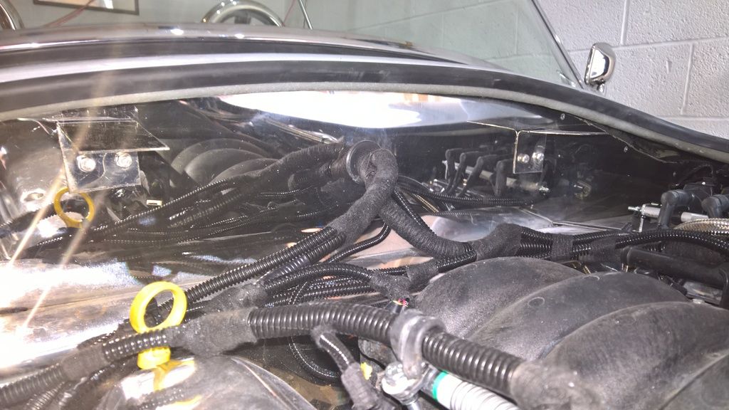
As the LS engine has a sensor behind the starter motor I had to finish drilling the hole in the bulkhead to pass the wiring through for the ECU. A simple 35mm hole and the lots of careful/forcing of the wires to get them through the hole followed.

Once they were all in the engine bay and the cam sensor was connected it was time to move onto batter wires.


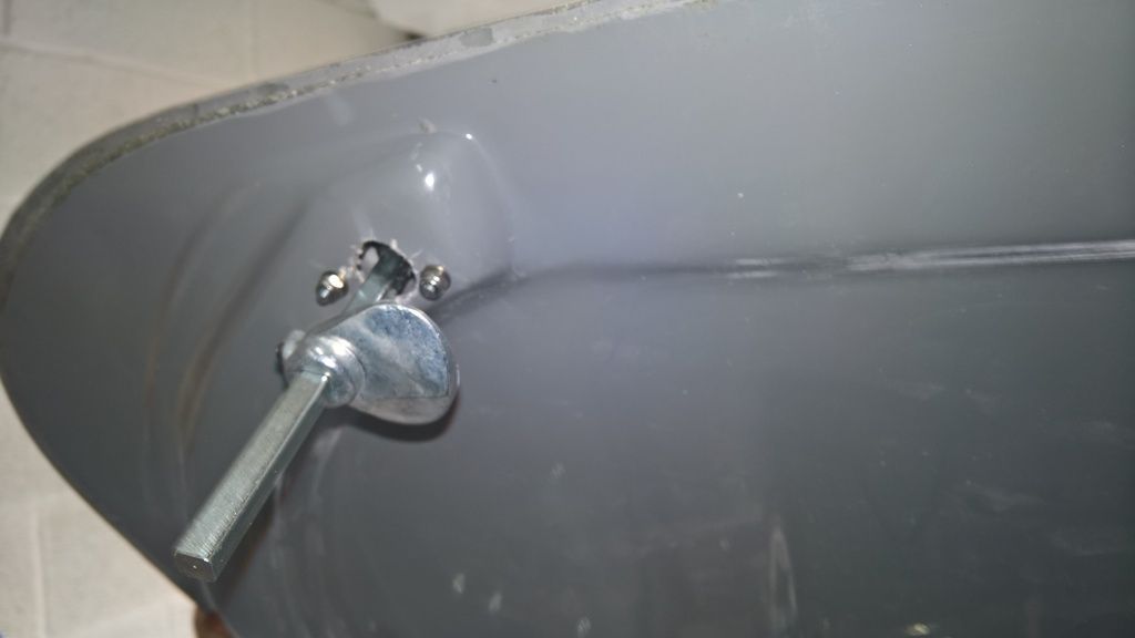
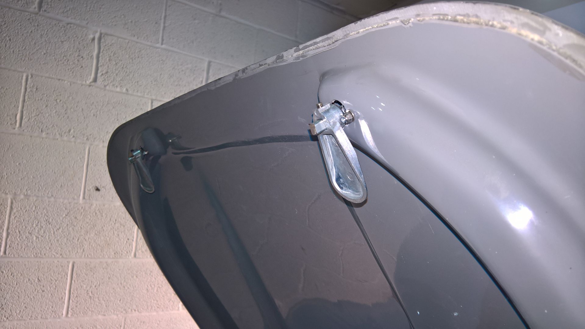
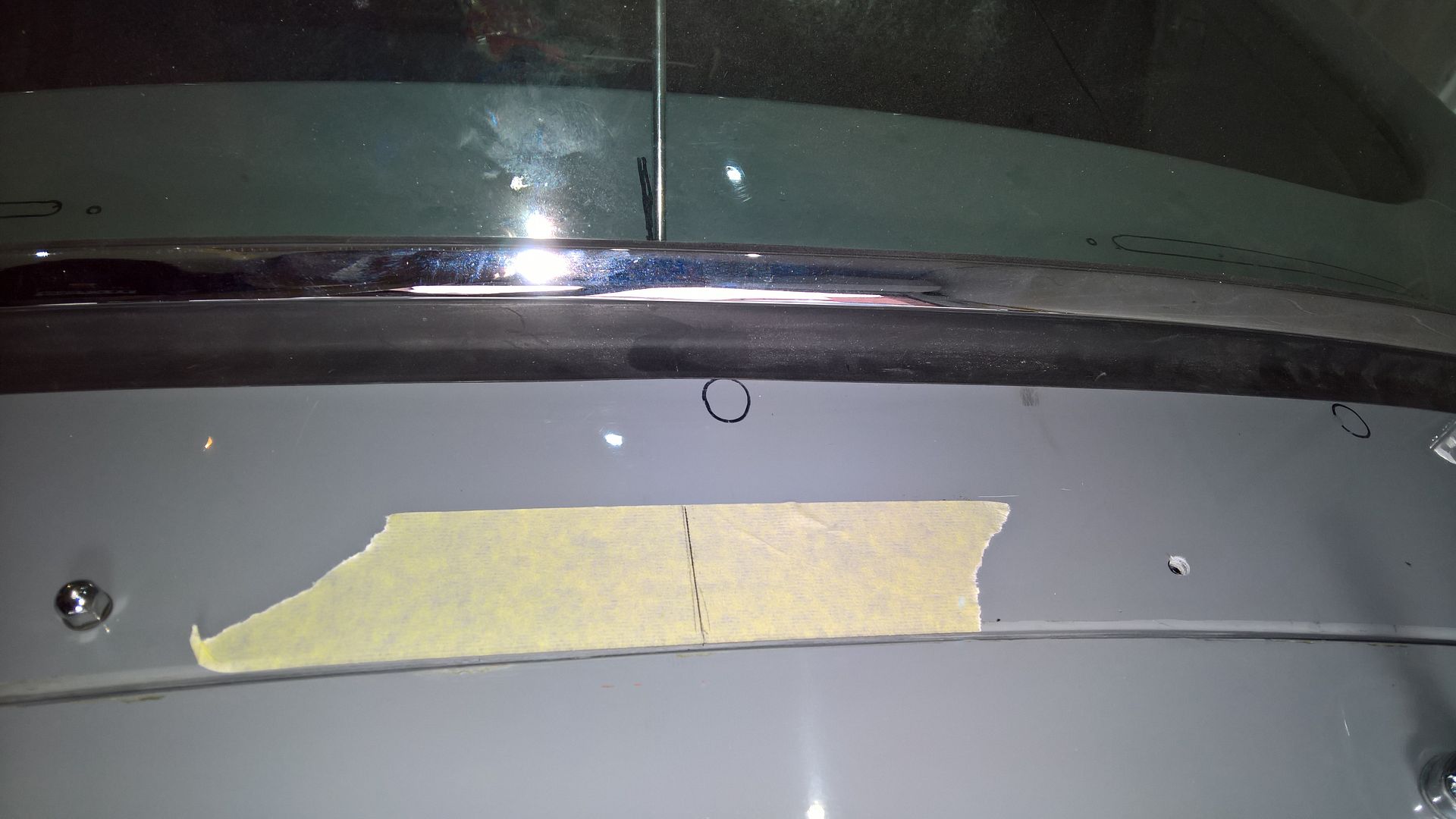
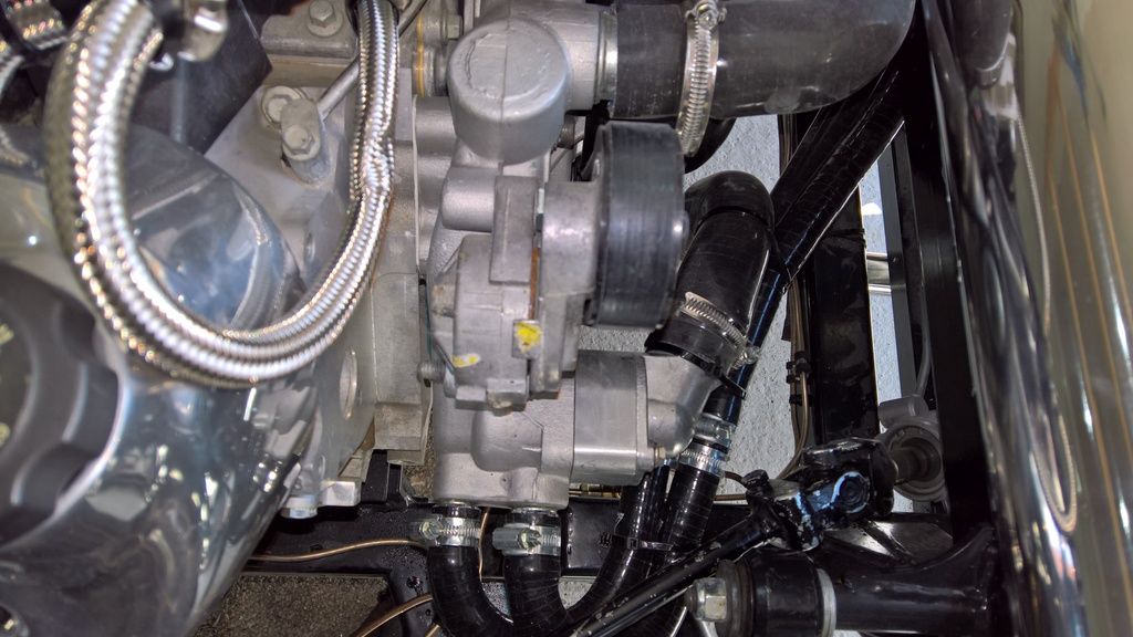
This included the battery positive, earth cable and AK loom to the starter motor and what become obvious very quickly is that I needed to make additional holes through the body (near where AK put their 1 inch hole). This was not easy as you have to kneel in the drivers seat area and crawl into the footwell then drill sideways on. This is a manoeuvre even a contortionist might struggle with and being a man of larger proportions made this even more difficult. Once complete it was easy enough to connect the wires as follows:

1) White AK loom wire to starter solenoid
2) Red AK loom wire to main starter connection
3) Red thick battery positive wire to starter main connection
4) Earth thick battery wire to engine block

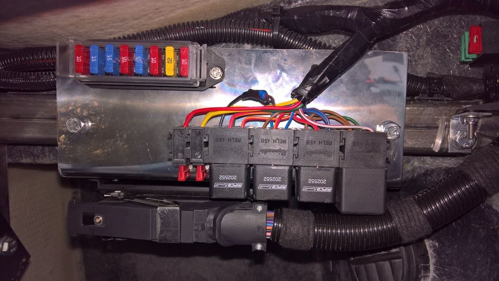
Some of you may be asking why I haven't run a second battery wire from the alternator in this stage. This is because I am mounting my battery cut-off switch near the drivers side scuttle bars. The wires will therefore go:

Battery      >
                      Cut Off Switch   >  Starter Motor & Powered Accessories (e.g. ECU)
Alternator  > 

This design does two things; first if you have an accident and cut the power it will cut the engine. The standard AK design (where you put it on the negative) could allow the car to earth out (on another car for instance) and it would carry on running.

The second thing this does is that it addresses a problem I was advised about by Dave from Canems ECU who advised that in many of the car electrical issues he is asked to diagnose, the problem is typically a bad earth caused by these cut-off switches, whereas when they are on the positive feed the car seems to be much better.

This is also the reason I have run a main earth wire the length of the car to attach to the block as it will guarantee a good earth connection. The wire attaches to the block with a smaller wire also to the chassis to aid earth of anything that is attached to the chassis at the front of the car.

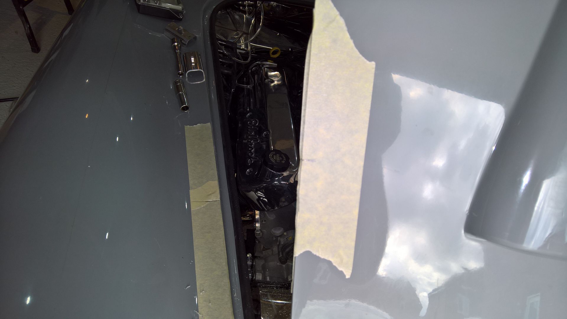
Once the starter motor was bolted into place it was time to move back to the top of the engine. It didn't take too long to connect all the sensors back into place following which what seemed like an age to clamp it all into place and loom conduit and tape where necessary to tidy it all up. As with anything a job can be done quickly but attention to detail makes all the difference in the end result.

I got lucky and the Edelbrock cover fitted perfectly with no fettling required - it's nice to have at least one easy bit of the build :-)

The last job I managed to achieve was running the breather pipes for the valve covers. The LS engine has enough breathers to connect them with a small 4 way adaptor to the air intake without using the AK inlets so I have just capped them off with rubber c
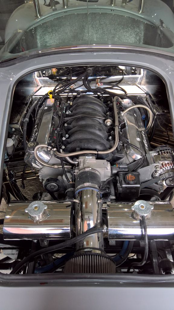
aps.

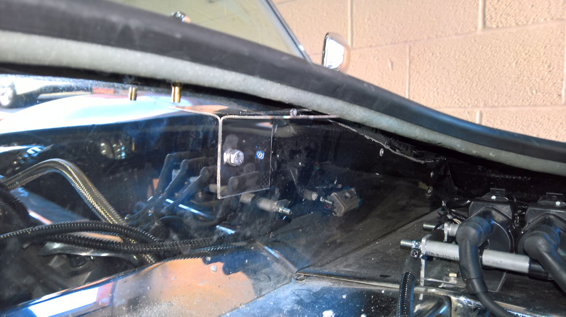
Like I said earlier - there's no much to show that can easily be pictured but here's a picture from the top of the engine.

There is still a few jobs left to do in the engine bay such as:

1) Make and fit a coil relocation bracket
2) Make and fit the HT leads
3) Extend the lamda sensor wires as my cable route means they are a little short
4) Attached the water pump hoses to the heater
5) Clamp the heater wires in place
6) Attached the steering column
7) Fit the bonnet

I have a couple of days off working coming up next week so hopefully I'll make good progress then.