Sunday 24 July 2016

Customising the AK Loom

Now I need to move onto re-wiring the engine bay and the first job is to customise the AK loom.

This is for two reasons;

First of all I am just not happy with the alternator charging wire that AK provide. Its a thick red wire which runs from the alternator (along with the blue wire) down the loom conduit to the starter motor (where there is two red wires and a white wire). This is not because its substandard in any way but I have installed a high rated polished alternator that outputs 150 amps (typically these run at 110 - 130amp) therefore I wanted to use proper battery wire rated to 170 amp. Removing this wire is fairly easy, you just need to remove some of the insulation tape on the loom and pull the wire out then re-tape the loom.

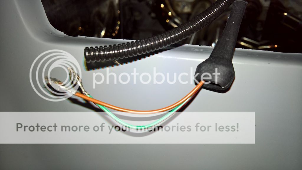
The next change is to cut off the branch of the loom that goes to the tacho as I have installed an electronic vehicle speed sensor (VSS) on the T56 gearbox. I haven't removed these wires entirely, I've just taped them up and put them into the main loom conduit, just in case they were ever needed in the future.

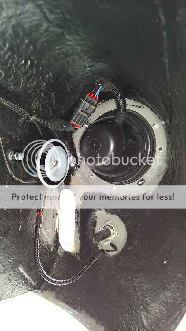
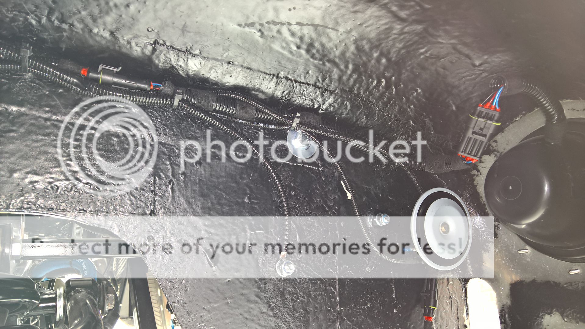
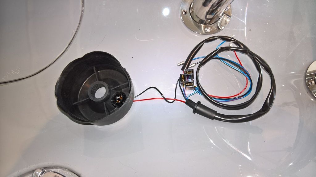
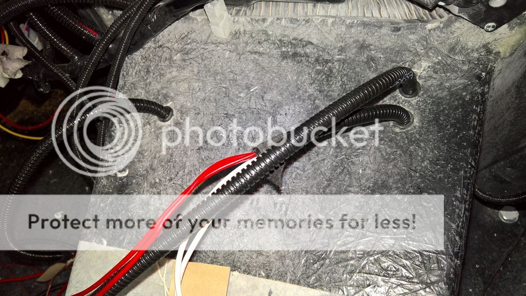
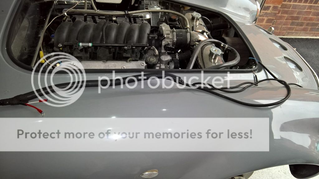
The picture below shows the VSS wire, along with the reverse lockout wires, reverse light wires and fuel pump positive wire which I have fed through the tunnel to behind where the dash will sit. These will be wired in at a later date. 


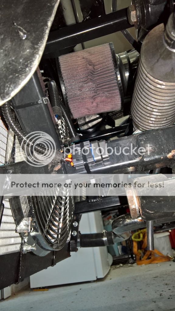
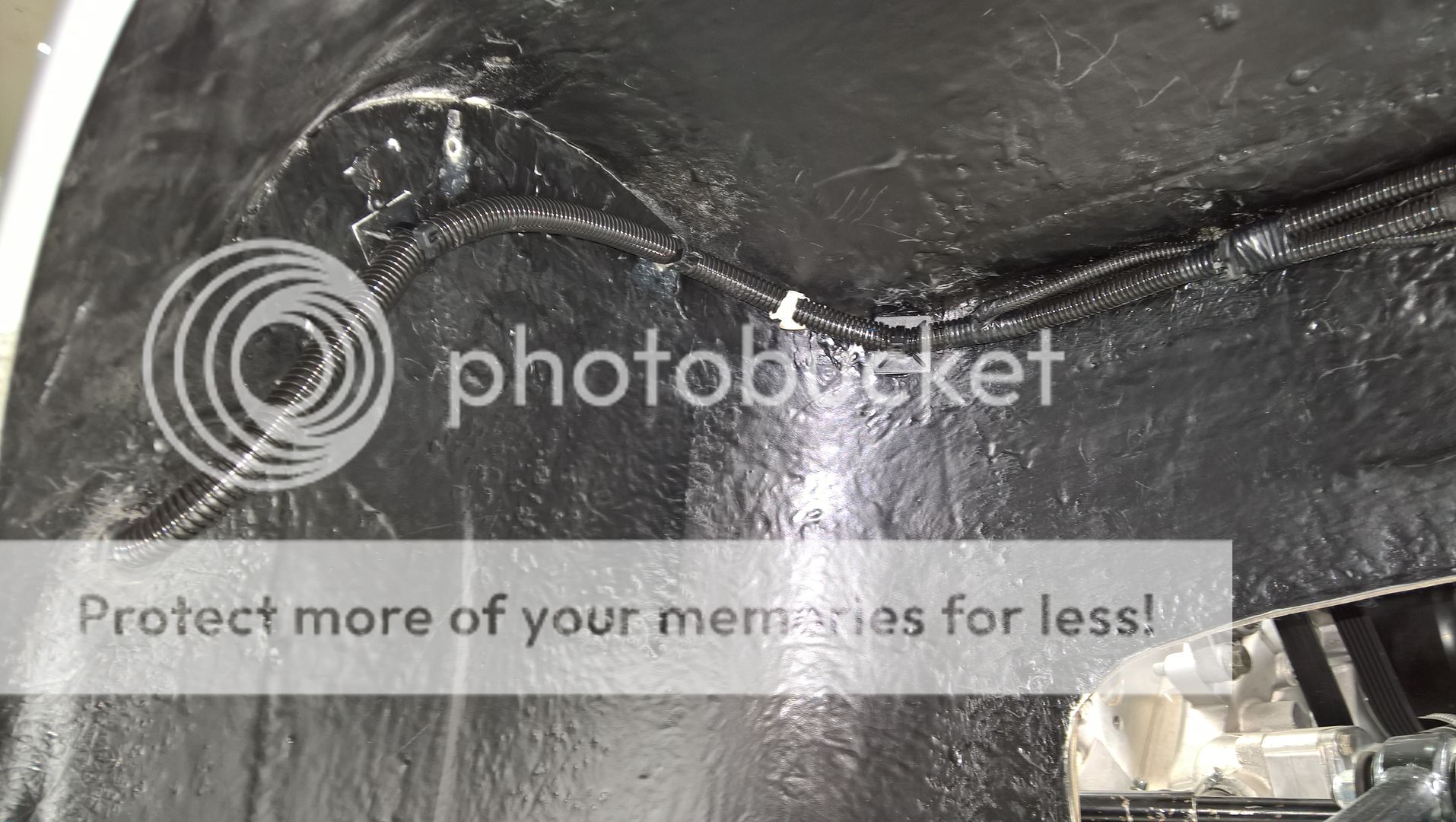
Finally, I added a bit of thicker conduit on one section of the loom. This is simply to make it easier to attach to the engine bay as it goes up the side of the engine block. 


Next weekend will be working on routing the battery wires into the engine bay and from the alternator to the starter motor. 

Diff Plate

Its funny how when you order the right parts jobs seem to get done :-)

It turns out the diff bolts I needed were M12 x 50mm x 1.25 thread (extra fine thread) so once these arrived I could get on with the job. 

AK put a swirl pot on the tank so even with the diff plate there is some of the fuel line below the protection of this plate although I am not too concerned as I have used braided hose which will offer some protection. 

The plate has three functions.

1) To offer some protection to the fuel lines in case the car grounds out on speed bumbs etc.
2) To give me another place to be able to secure the fuel lines so it meets the IVA requirement for distance between fixings (the small 5mm bolts you can see are securing 4 p-clips).
3) To be able to secure the lines far enough away from the diff so that I don't get too much heat from the diff into the fuel lines. 

It looks like its rusty in the picture but its not. its actually stainless steel.


The regular followers of the blog will know this was my last job on the rear of the car........although I forgot to include the gas struts, which I have now received from AK. 

I intend to fit them once I am in a position to fit the bonnet so for now I am going to tell myself the rear of the car is done as it makes me feel happier about progress :-)


Saturday 23 July 2016

Front Nudge Bar & Splitter Wing

Fitting the front nudge bar and splitter wing is one of those tasks that requires a fair bit of adjustment and to make it worse the manual states that you must fit this only by eye as the measurements are likely to be out due to the body not being symmetrical.

If you order the nudge bar and over-riders they come as separate parts and need to fitted together. This requires 4 x M8 bolts with spring washers and normal washers. I had 35mm bolts so I needed to trim these down to 25mm as the fitting is quite short.

The parts you need are:

2 x Over-riders
1 x Nudge Bar
1m of 10mm threaded bar
1m of chromed tubing to place over the bar
12 - 16 half nuts

Cut the threaded bar into 4x 25cm lengths and then cut the chrome tubing making 4 x 17cm lengths.

I drilled the top left hole roughly where AK had marked on the bodywork and then placed the over-rider in position. This allowed me to put into place one of the brackets that come with the AK kit so it could be marked out. For ease of adjustment I only drilled the top hole in the wing and made an elongated hole in the bracket for the threaded bar. This was then attached with an M8 bolt and nyloc.


The next task was to make a paper template of the fitting and then mark and drill two holes in the first over-rider so that the nudge bar could be bolted together.


Connecting the two parts together is again a mixture of measurements and by eye, but its fairly straight forward. Just take your time.


Once you have the nudge bar bolted together, offer it up to the car with just the top threaded bar attached in both over-riders and repeat the process of attaching the top bolt in the bracket.

Then put into place the bottom threaded bars, mark out the holes on the bracket and align the nudge bar how you want it. I have done mine about an inch away from the car but some people prefer it much closer.

Now comes the fettling bit which frankly takes some time and involves taking the bar on and off a few more times.

You need to sand/file the holes and add the chromed tubing ensuring nothing catches on the bodywork when its fitted. I chose to add a half nut onto the threaded bar before adding the tubing, then to put another on after the tubing to hold everything in place. I then placed another half nut either side of the bracket.

I checked with AK and they drill the holes and leave a small gap around the chrome tubing for paint but they don't use grommets.

The picture on the right also shows the splitter wing bracket. This is simple an angle bracket with two M8 bolts through, again purely fitted by eye to make the splitter wing look level.

As it was warm today I decided to work in my shorts rather than the overalls something that caught me out when I ripped them on the grate at the front of the garage. The Mrs wasted no time in picturing me with the duck tape trying to hold the shorts together.


Anywho.... once everything aligns how you want it just add the final nuts, tighten everything up and job done.


Friday 15 July 2016

Side Repeaters

I was caught out last week when I came to wire the side repeaters as I realised you need a specific electrical connector for them. I had bought the repeaters from S&J Motors but luckily CBS (Car Builder Solutions) provides connectors for them for about £7.

They arrived today so I spent a few minutes wiring them up.

One thing to note is that you need to wire in the lights from the engine bay or through the side louvre holes. Do not put the wire through the hole for the lights as the connector wont fit back through!

Simply put the rubber sleeve onto the wires, crimp on the two metal contacts and slot them into the connector block.


Fan Wiring

The AK loom comes with wires for the fan; 1 wire for to go through the supplied in line fuse and onto the blue connector of the fan and two others to go to the temperature sensor. The black earth from the fan can just be earthed out on the wing mounts.

As I am using the Canems ECU, which comes with a switched earth for the fan I don't need to use both the wires at the fan end, just the one with the inline fuse so my first job was to tape off the unrequired wires and hide them in the loom conduit.

Next job was to fit the inline fuse and earth to the wing mount chassis bolt. Add a bit of conduit and then time to zip tie into place.

I have ensured the inline fuse is down at the bottom of the chassis near the wishbone in the wheel arch so I can change the fuse easily if it breaks.

In order to make the fan work at the right temperature all I need to do when I do the dash
wiring is find the black wire from the fan relay, cut it and attach it to the Canems ECU fan output.

This guarantees the fan will kick in at the right temperature as the Canems ECU uses the GM temperature sensor on the LS6 block. It also saves a lot of hassle trying to use the AK method of inserting a probe into the radiator coolant tubes or fitting a boss to the radiator.

Sunday 10 July 2016

Front loom legs & Horn

Whilst I await the bolts I have ordered to fit the diff plate I am making I decided I would tackle fitting the loom into the front wings and hooking them up to the headlights and sidelights.

Starting with the offside (drivers) wing I fed through the loom leg and then fitted AMP Weather proof connectors to the headlight and sidelight wires on the loom. Cue a visit from Mr Cockup, something I would not notice until later down the line.

I proceeded to add AMP Weatherproof connectors to the headlight and sidelight, making an earth wire for the sidelight which fitted with an M5 insulated ring connector.

The horn, which is just a simple low tone, twin terminal universal horn from e-bay (cost
about £7) just has two 6mm spade connectors which connect to two 6mm female spade connectors which you fit onto the wires on the loom. Fitting the horn itself is very easy as you can just drill an 8mm hole in the wing and put a bolt through.

Then it was time to push all the wires into place and tighten up the zip ties.

And there I was all pleased with myself for a job well done.


But hang on.....

Suddenly it dawned on me that I needed to disconnect the headlight for the paint job, but the AMP connector was half way down the wing zip tied into position onto the lengthy wires from the headlight loom.

Why I hear you ask?

Well, in order to ensure that the earth wire is in the right position and that the horn wires fit without too much excess that's simply where the wires ended up.

What I hadn't realised is that I needed to extend the loom wires using the long loom from the headlight and then fit the removable AMP connector much nearer the headlight. So another hour was spent cutting the loom nearer the lamp and fitting another connector there so the headlight could be removed for paint.


Suffice to say I didn't make the same mistake in the other wing, instead I extended the wires using crimp connectors and then fitted the AMP connector next to the headlight.

I will post pictures of the other wing once done as I still need to fit the fan wire and finish tidying up around where you need to cut a slot for the alternator.

For the regular readers - I have now received the quick connect battery terminals and fitted them too so the last jobs on the back end of the car are the diff cover and gas struts (I forgot to add gas struts to the list before). I'm just awaiting the struts from AK but I'll wait to fit them until I am ready to fit the bonnet which will be a few weeks yet.

Sunday 3 July 2016

P700 headlights & Sidelights

This is just a quick post to talk about the P700 headlights as someone posted on the Cobra forum saying these didn't come with sidelights.

This may be true from where-ever they got theirs from but I wanted to clear the record for my readers by stating that if you buy them from S&J they do come with sidelights pre-fitted.


S&J provide the headlamp unit and a separate wiring/light loom as shown in the picture below.


All you need to do is cut off the round rubber bit (you can discard this), attach the red and black wires to the red and black wires on the sidelight bulb with a connector of your preference and then assemble the headlight as normal.

I haven't wired them onto the loom yet but I hope to get to this during the week or next weekend.


Saturday 2 July 2016

Battery Tray Under a Tenner

It never ceases to frustrate me how much some very simple parts are for the car. The battery tray is one of these items as AK will happily charge you £40 for a tray, which is nothing more than a bit of welded angle iron which is painted black.

So I decided I wasn't going to go down this route and instead asked around my friends and luckily someone came up with some spare angle iron.

Basically the tray can fit any battery you wish to put in it as you just need to cut the iron into lengths that suit your battery size.


Then, place the lengths into a square (ideally using a set square to get the corners right) and check your battery fits. If so, use Sikaflex to glue the square together holding in place with G-clamps or similar.

Once set, wire brush down if its old angle iron and treat with POR-15. I used some left over caliper paint that I had.


You'll notice that I have trimmed the iron to leave to slots raised up from the rest of the tray so I can feed the battery strap through.


I have also added some foam tape to ensure the battery has a snug fit and no vibration.

Fitting in place was just a case of drilling 4 x 6mm holes in the boot floor. As the angle iron has pre-drilled holes it made the job a little easier.

The strap came from e-bay for a few quid and just needed feeding through and adjusting to the right length.

The last job in the boot now is to fit the battery terminals. The ones I have don't fit the insulated terminal covers so I have had to order some more.


Fog and Reverse Lights

I managed to get around to mounting the reverse and fog lights onto the nudge bar. I'll improve this following IVA but I don't want big square holes in the body.

This was an easy job, just take 4 1" rubber lined P-clips and some 5mm aluminium flat bar. Bend the bar and use the pre-drilled holes to mount the lights.

The lights use 5mm hex bolts with nylocs and the P-clips 6mm with nylocs.


A little conduit to protect the wires going underneath the bodywork and all done. To say how ugly these lights are I can live with how this looks for now.

Weirdly in the photo to the right it looks like the lights are in the body - how strange!