Wednesday 30 September 2015

Rolling chassis complete .... well nearly :-)

A few small jobs were required to complete the rolling chassis so I my target was to get these completed during the past week.

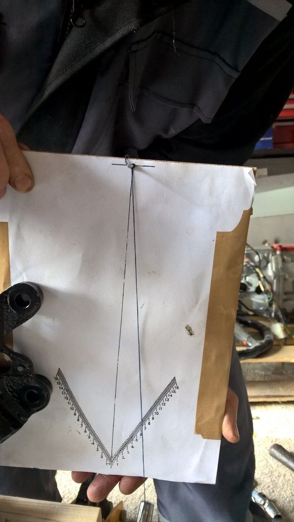
The first task was to complete the back axle setup. The speed sensor rotator had arrived from Jaguar although just as with the first one the holes didn't quite line up and it needed some small adjustments. I bought this as I needed a 2mm shim for the drivers side axle to get it to between 0 and 0.5 degree (top in) and the smallest Jag do is 3.5mm for that side.

After getting one for the other side of the car and confirming it is 2mm thick I decided it was the perfect solution. It took longer to re-level the car than it did to fit and I was soon putting the suspension into place.


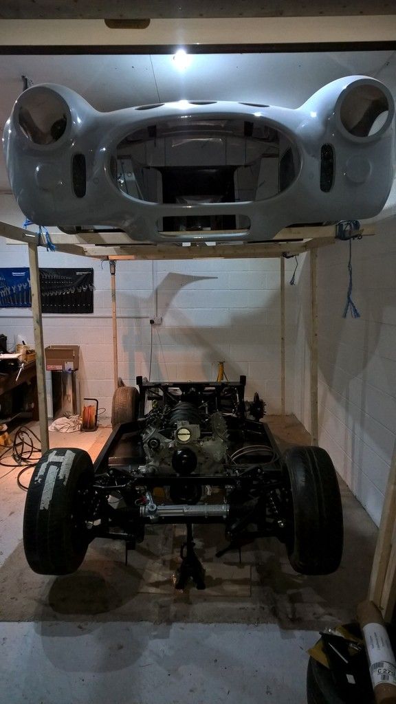
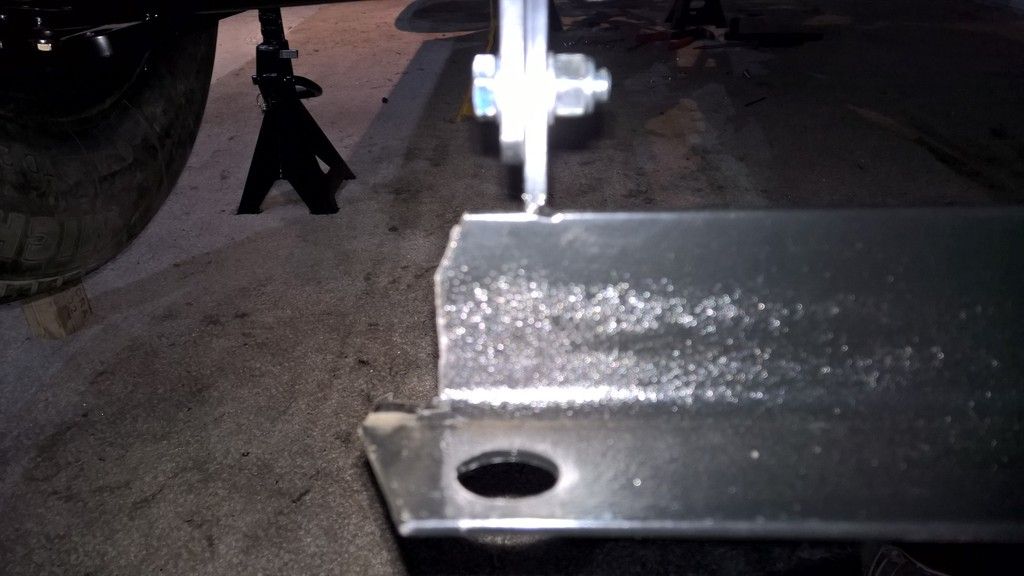
Next up was to fit the radiator. The lower bracket went on easily but the lower radiator outlet fouled on the corner of the bracket.
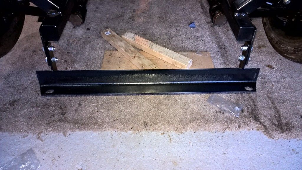
After checking with AK this can happen and its just a case of cutting the corner of the bracket. I had to take off a reasonable amount to make it fit so I adjusted the opposite side of the bracket so it matches and looks correct.

You need two rubber gromets for the radiator to sit on which are not provided with the kit and after checking on the cobraclub forum I found a link to this part at rimmerbros . At £1.30 each it wasn't worth the effort of making my own grommet but if you are interested in this approach then Jon at AK gave me the following advice.


"You need to make two top hat shaped grommets to fit over the pegs on the radiator , I use two different size hose, 1 x 10mm i/d hose to fit over the peg and another piece to fit over that tube cut about 4 or 5mm thick."

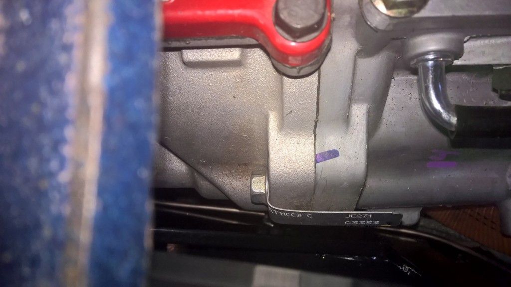
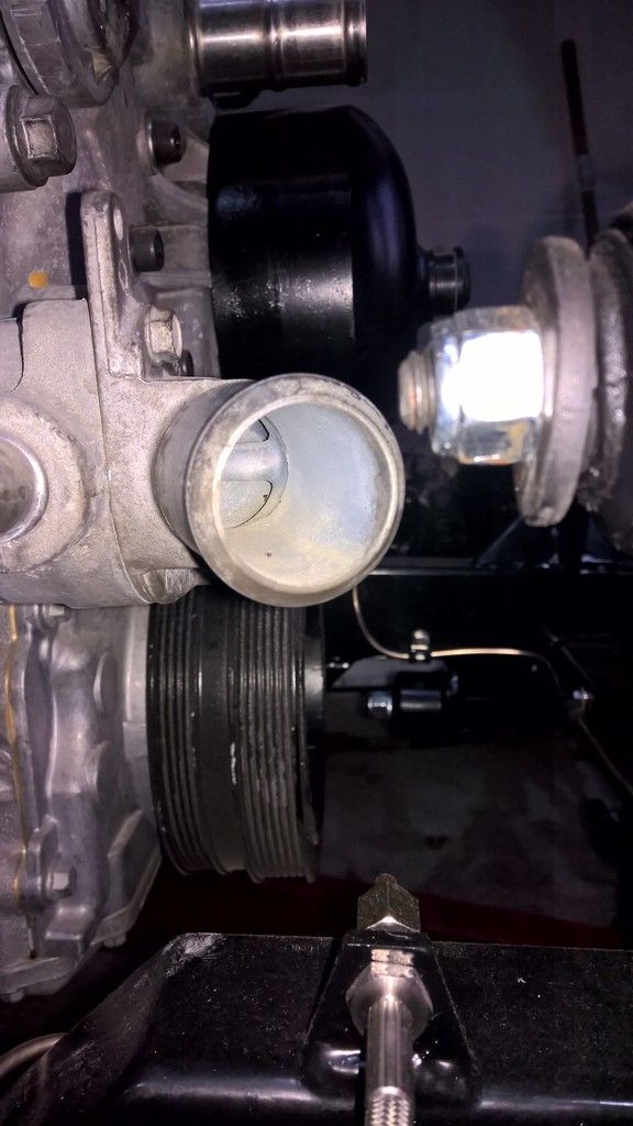
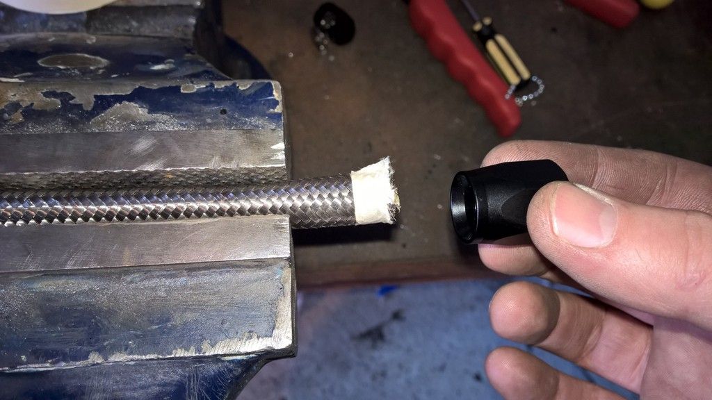
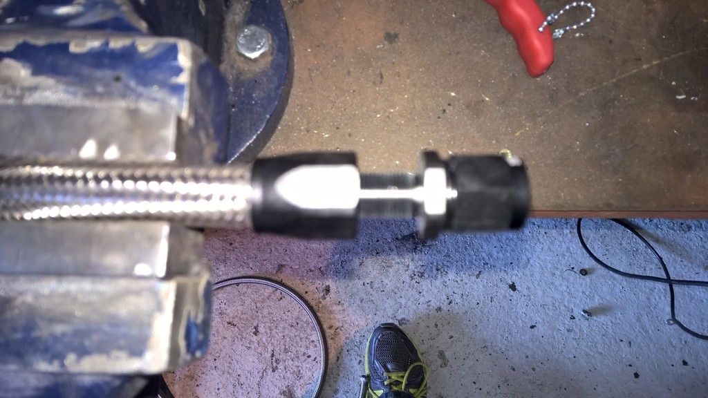
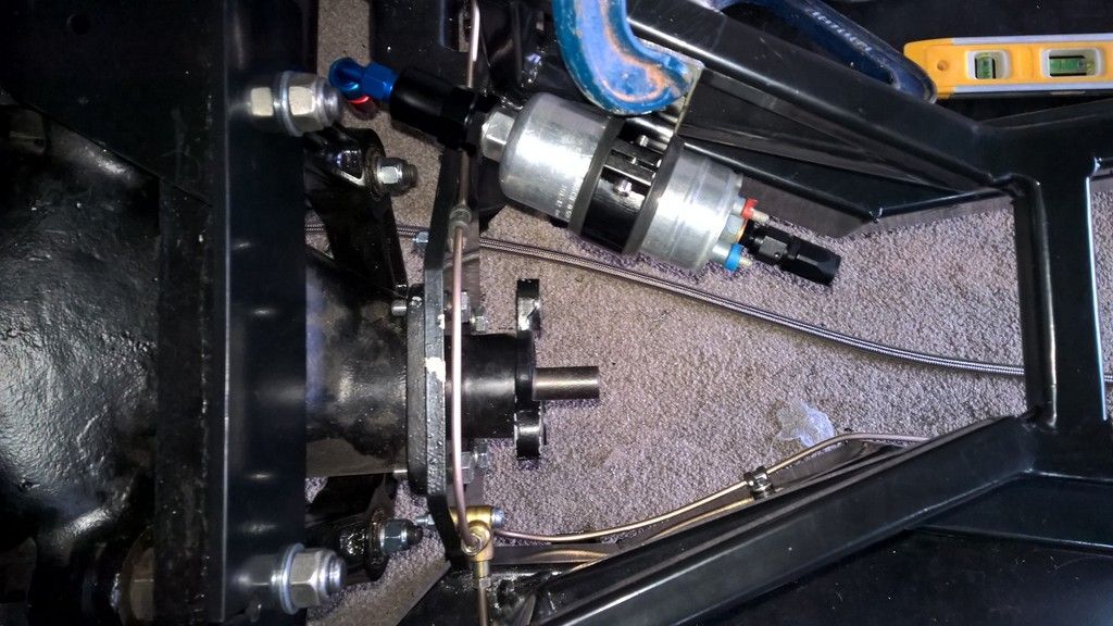
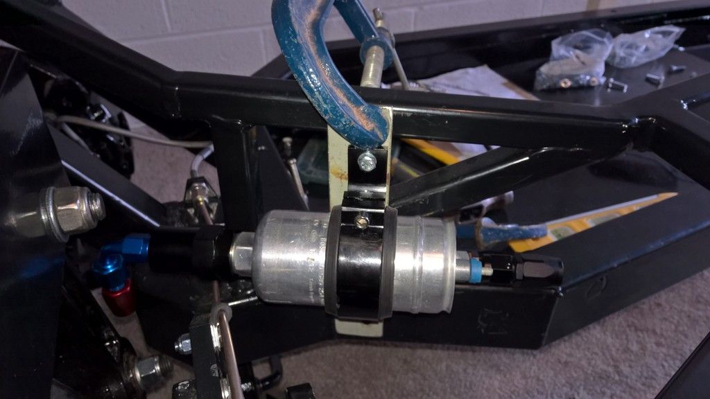
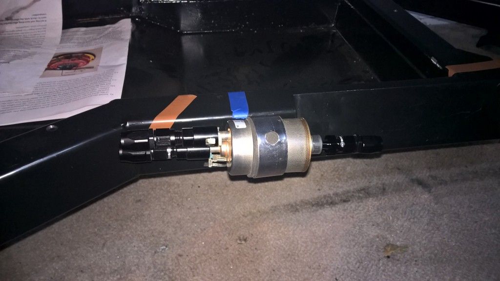
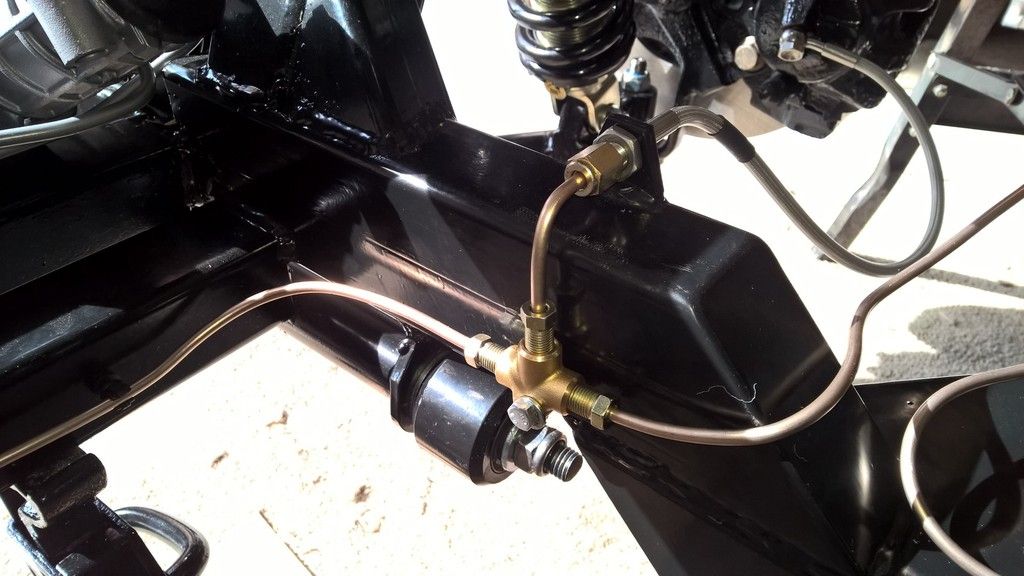
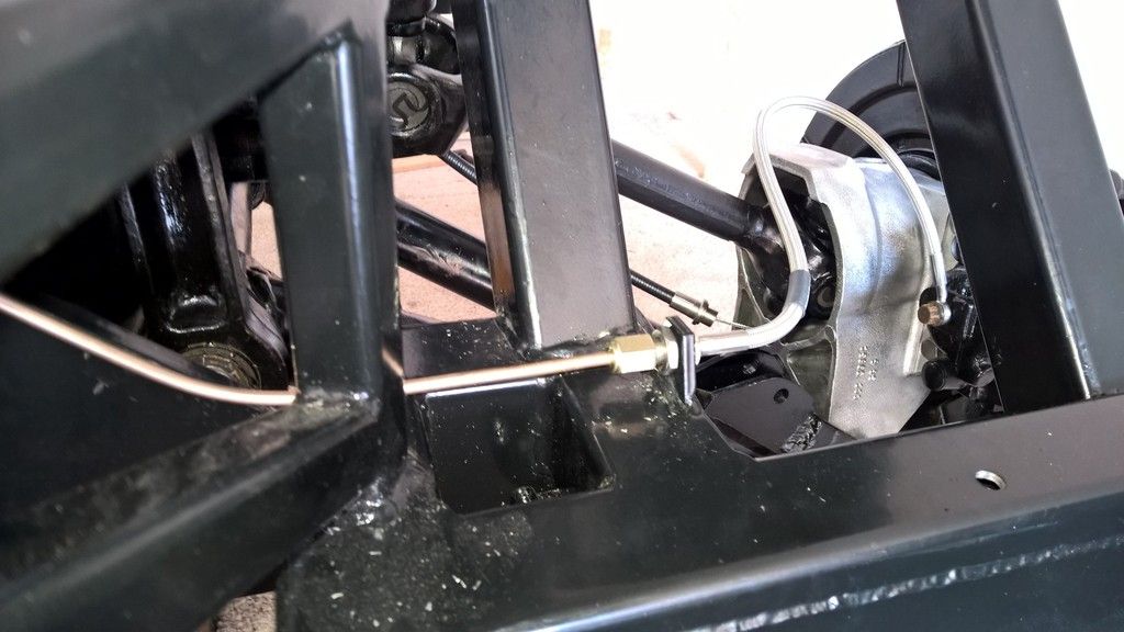
Next was to replace two M10 hex bolts in my bell housing with Allen bolts. This was because the bolt head was fouling on the housing followed by changing one of the connections on the end of my fuel line as it was also fouling on the housing (see updated Fuel lines post).

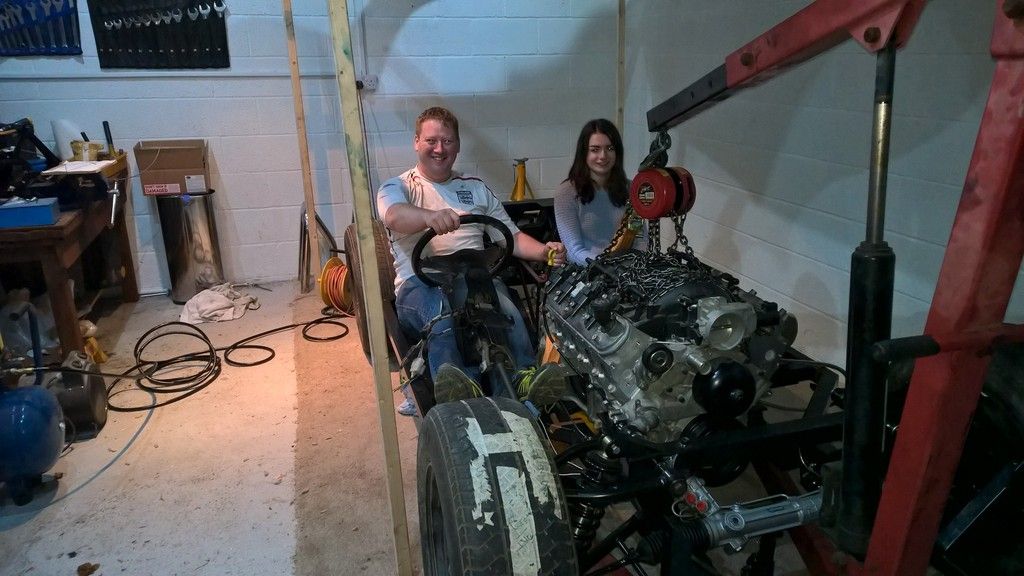
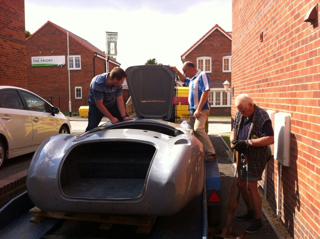
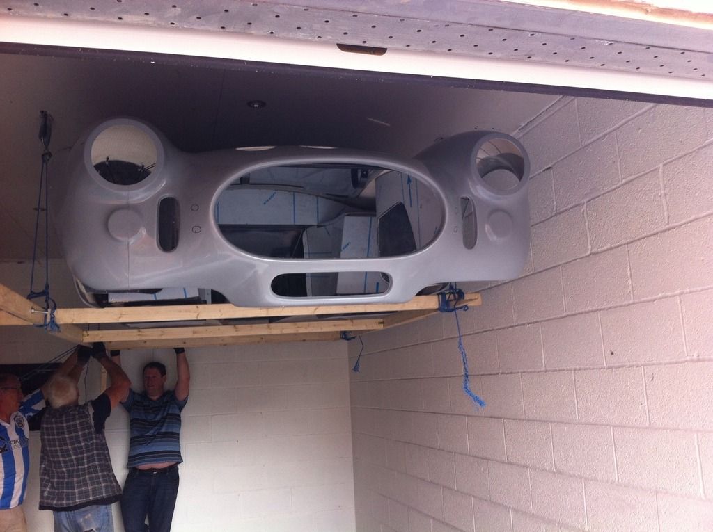
Whilst working on these tasks Si Smith arrived along with the Catherine and friends to see how I was getting on. It gave a great opportunity for the kids to see the finished article.


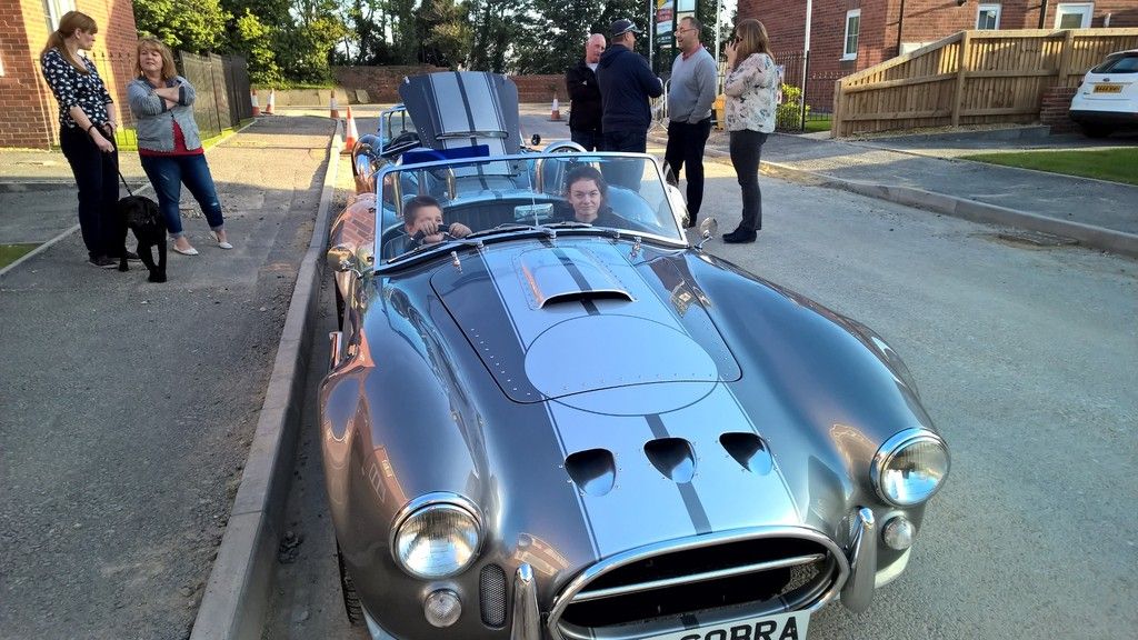
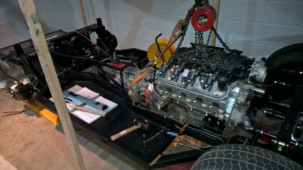
As we were discussing some of the challenges I have had they all confirmed what I had been thinking which was that my engine was sat slightly lower on one side. After measuring we confirmed this to be 5mm; a small amount but viewable to the naked eye. It appears as if the mounting brackets supplied by AK have a slightly different angle on side. This is easily adjustable and I am just waiting for a 5mm aluminium plate to arrive which I can use as a spacer. I picked this up for less than £2 on ebay.

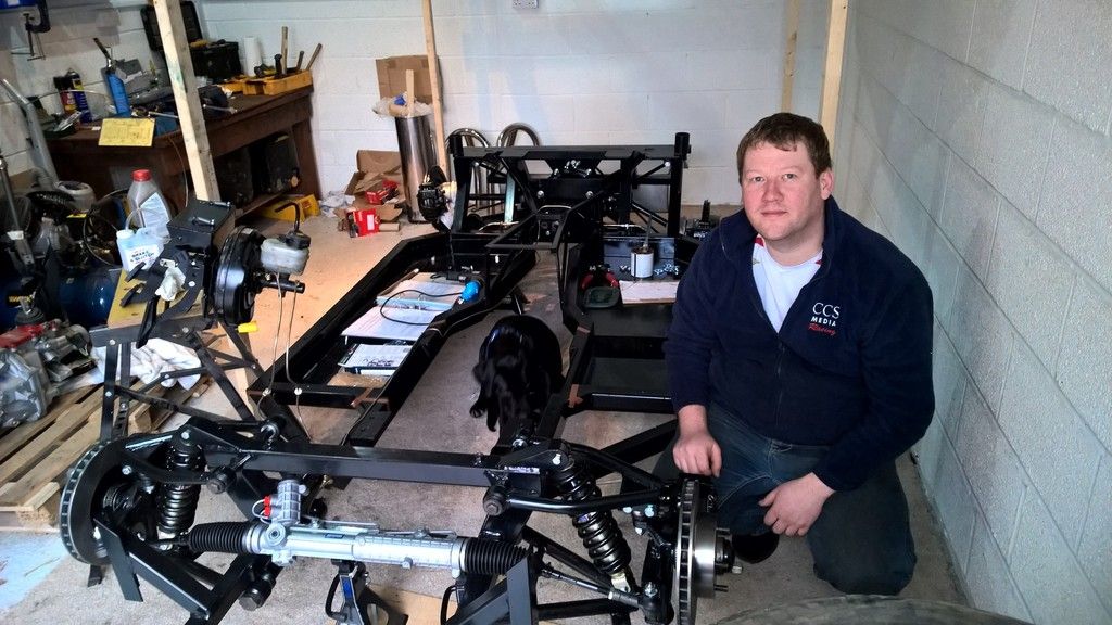
All that is left now is to level the engine, bolt the gearbox mount, touch up the chassis with por-15 (from where I have drilled etc) and order the prop shaft and the rolling chassis is done.


Thursday 24 September 2015

The engine is in


I have figured out the problems with the engine/gearbox alignment and water hose position. The holes on the passenger bracket were 1cm further back than they needed to be, so after confirming it was ok to elongate the holes with AK I re-drilled and set about lifting the engine and gearbox back into place. It now aligns perfectly.

The water hose connection / thermostat housing simply needs unbolting and turning 180 degrees. AK do this with all LS engines.


After such a milestone my daughters and I couldnt help but have a little fun and pretend we were driving. This was the first time I had actually sat in the chassis like it was a car :-)


The gearbox mount still needs to be attached and I'm still waiting for one final shim from Jaguar to finish the back rear suspension. Hopefully it will be a rolling chassis by the end of the week.

Sunday 20 September 2015

Progress so far

After a week of hard work, running around for tools  bolts and washers I have made some good progress as shown below:


Some things on the build went really well, just as the manual shows. For instance the front
end of the car went together easily, the caster was spot on straight away and it was complete in a day.

The back and engine was a different story.

I needed 2mm of shim on the drivers side, 6mm on the passenger. Jaguar dont do a 2mm shim (and right/left are different). AK do however do 1mm shims but I realised the
diff normally has a speed sensor on the left which is 2mm thick. This was much cheaper than the Jaguar shim (£10 vs £35) and it tidies up the diff a little so I installed one of those on the drivers side to solve the problem

Another speed sensor plus a 4mm shim on the passenger side should achieve the required offset so this is on order.

Waiting for the shims causes a delay so watch out for this. There were major issues getting the diff and diff tie bars to line up. Both tie bars needed to be modified to fit into their brackets, the plate which takes the top rear bolts on the diff wasn't well shaped at all and needed quite a bit grinding off to allow the diff to raise into position and the differential rear carrier needed the holes adjusting to get the tie bar to line up.

Additionally, the kit doesnt come with enough 1.5" x 7/8ths washers so I strongly recommend getting 10-20 of these to save some time running out to the hardware shop. 

You'll also need additional M12 and M14 nyloc nuts, 7/16ths bolts for the Diff, 2 of M16 x 2 nuts for the diff and plenty of washers and M10 x 35 and 70 bolts, nuts and washers.

I also used M5 and M6 Rivnuts, bolts and spring washers for various jobs such as brake and fuel lines. 

Finally you will need some threadlok.

Getting the gearbox to mount to the engine was a bit of a headache. Eventually I took advice from Brian at Roadcraft. He explained I needed to remove the outer bearing on the crankshaft for the LS6. Everything went together and it was lifted into position. 


Its currently hitting against the chassis on the drivers side so something is out of alignment and the water pipe mount will foul on the upper front wishbone. I'll post solutions to this when I get chance. 

Progress will slow a little now as I return to work next week so will have limited time. 

Saturday 19 September 2015

Fuel System

I spoke to AK about what they do before starting by fuel lines as it wasn't clear if I would have room. Mounting the pump in the "normal" place at the back risked fouling on the prop shaft. Mounting at the front meant long return fuel lines and no room from the regulator I had purchased.

After a bit of a think I came up with the following solution.

The parts needed are:
  • -6 AN fuel line (approx. 15 ft)
  • Bosch 044 Fuel Pump
  • Some metal strip to use as a mounting bracket
  • 4x M8, 8 x M6 and 3 x M5 Riv nuts, bolts and spring washers
  • 2 x AN-6 90 degree corner swivel hose fitting
  • 4 x AN-6 Straight Hose Fitting
  • 1 x AN-6 Quick Connect 5/16" Hose Fitting
  • 1 x AN-6 Quick Connect 3/8" Hose Fitting
  • 3 x AN-6 15mm Clamp Finisher Hose Fitting
  • Dash -6 Bosch 044 Outlet straight fitting
  • AN-6 Bosch Inlet M18x1.5 30 Micron Filter
  • Standard GM Compatible 58 PSI Filter Regulator
The fuel line and regulator came from summitracing and the connectors from torque products. I used the standard GM filter regulator as it works at 58psi which is what the LS6 engine requires. In addition it is readily available at just $35 from summit racing and as it has a built in return valve it saves on additional connectors and cost. 

I used AN-6 fuel line instead of the 10mm I/D hose recommeded by AK as it is slightly smaller and therefore more pliable. In addition, Tim Adams racing advised me this size could provide enough fuel for over 900BHP so there was no need to go as big as 10mm I/D. 

Making the pipes is fairly straight forward. You just have to take your time, one pipe at a time attaching them into place before you move on. This means taking pipes on and off as you go but it means there is less chance for error.

To make a pipe:
  • Wrap some masking tape around the pipe and then cut with an angle grinder and cutting disc. The tape stops the pipe from falling apart.
    • NOTE: if you get lots from fraying on the pipe then re-cut it as it will be more pain than its worth.
  • Hold the pipe in a vice and offer up the first part of the connector. Use a small flat screw driver to work the end of the pipe into the connector. This takes a bit of effort as you push/screw the end cap onto the pipe without damaging it but its not overly difficult.
  • Screw in the second part of the connector. I found a good method was to clamp one spanner in the vice with the ring end out of the vice. Place first part of the connector in the ring and then hold the pipe with one hand whilst turning the second part of the connector with another spanner until its right in.

I connected the filter to the bosch pump and made a bracket to attach it to. This was so I could mount it at the back near the diff but higher up than the prop shaft so it easily cleared the brake pipes. NOTE: the bottom of the bracket needs a spacer in it as it is offset to the tunnel part of the chassis.

I used M5 Rivnuts and bolts with spring washers and threadlok in the tunnel frame and M6 Rivnuts with bolts, spring washers and threadlok in the main chassis beam. All P-clips were rubber lined and spaced 10" apart.


The standard GM filter regulator was placed towards the front of the chassis where the manual suggests putting the pump. 


Pipes were then made up running from front to back.

The tanks had to be lifted into place with a jack and then the "lugs" drilled out to 7mm, then tapped at 8mm. M8 * 35mm bolts with spring washers and thread lock was then used to secure the tank. NOTE: you only drill up through the first wall of the chassis tubing. Do not go through both walls (a.k.a all the way through)

Heres the final solution. 


Update 30/09/15 : I was unhappy later with the clearance from the end of the fuel regulator on the bell housing (the last connector to the right of the picture above) so I changed the connector for a 90 degree bend fitting instead. Parts list at the start of this post has been updated so is correct. 

Brake Lines

Running the brake lines is a fairly straight forward job, if you have the right tools. I used the following:

  • Kunifer brake pipe (rather than copper as it handles newer fuels better)
  • A brake pipe flaring tool I borrowed from a mechanic I know
  • Various unions bought from carbuildersolutions
  • M5 Rivnuts, M5 bolts, Spring Washers and Thread-lok
  • 3/16ths rubber lined p-clips spaced 10" apart
  • A 90 degree drill chuck bought from Toolstation for about £10
  • Some brake pipe clips (just to hold the cable in place until permanent fixings were added)
The key thing that I found was its all about having the right tool. The brake flaring tool I bought was very easy to use, made perfect flares straight away a every sealed up first time when I pressure tested it.

How do you flare brake pipes (using a tool similar to what I had)

1) Place the pipe in the bottom half of the mould, add the top of the half and screw the clam down ensuring the pipe is flush with the front for the mould.
2) The rule is do a single flare for a male connection and a double flare for a female connection.
3) line up the 3/16ths flare tool and pull the lever on the single flare (even if doing a double)
4) Without moving the pipe, and only if doing a double flare, move the tool across to the double and pull the level again.
5) Use a pin to pull out any swarf/metal shavings from inside the pipe.
6) When tightening in them up on the car do not over tighten. This is as bad as not doing them enough. They should be hand tight but without swinging off the spanner.

I then connected all the calipers, discs, brake flexis and pedal box so that I could pressure test the system. I left this pressurised overnight and once I was satisfied everything was ok a drilled and M5 Rivnut the chassis to fix the brake lines into place. 


Caliper Rebuild

A lot of builders shy away from rebuilding their own calipers usually siting the importance of braking as the reason; many use Ward Engineering and I must admit that if ease is your preference over cost or if you are comfortable with this approach then go for it.

However, I wanted to rebuild as many of the donor parts as I could myself.

Calipers are fairly simple items. There is a square cut seal (the most important bit) which sits inside in the piston housing. This along with a clean piston face is the bit that really makes it work. There is a dust boot to keep the whole thing clean and functioning well; finally there are the carrier pin rubber sleeves, bleed screw and brake pipe input hole.

My rear brakes are from the Jaguar X300 range whereas the fronts are the XJ40 (newer version). For those that don't know, it is important to know this when you get your donor parts as the XJ40 has two part numbers for discs and pads (etc).

The XJ40 is commonly M10 x 1 for the input thread, However if you have the X300 variant that I have on the rear of the car, they are M10 x 1.5.

Replacement parts are available from a number of places but I chose to get mine from SNG barratt as they do both Jaguar and cheaper alternative products so you can pick and choose the best route for you.

I am assuming that you have cleaned up the calipers and painted them with something like POR-15 caliper paint (I got mine from Frost.co.uk).

First install the square cut seal into the piston housing. Lubricate it well with brake fluid and ensure that it is seated corrected. It just pushes into place.


Next there are two methods of installing the boot and piston; the first worked on three of the calipers, however the 2nd had to be used for the 4th as the boot kept jumping out.

Secondly install the new bleed screw and tighten, then:

Method 1: install the boot into the piston housing ensuring that you push the rim into of the boot into the seal groove then lubricate the boot well with brake fluid. Place the piston (also lubricated well with brake fluid) over the boot and use an air line to blow air into the brake pipe input hole. If you have created a good seal around the boot it will inflate and try to push the piston out. Allow it to do this a little and it will expand and pop around the piston, you can then just push the piston in (you may need a clamp or brake piston retraction tool). Push the piston in fully and then work into the groove in the piston.

Method 2: Place the boot onto the bottom of the piston with the seal hanging off the bottom. Place the piston over the housing and work the boot into place gently. Once the boot rim seats into the housing you can push the piston fully in so the boot seats into the piston also.


Finally, blow a little air into the brake input hole (not too much) - just enough to move the piston so you can check the boot is installed correctly and apply a little rubber grease/copper grease/Vaseline to the carrier pin holes and push through your new carrier bushes.

All done.


Thursday 17 September 2015

Storing / Lifting the body

Many people simply put the body in the garden and AK are fine with this, however, for me the garden gate gap was too small to get the body into the garden (I would need a crane to lift it over the wall!)

So I needed a new solution....

What I had was a reasonable high garage ceiling, so I decided to lift the body up instead.

First and foremost I talked with the surveyors who built the garage to confirm it could take the weight and when they said yes the plan was put into action.

The parts needed for this were:

4 x 4" x 4" fence posts, long enough to span 3 roof rafters

2 x 1 tonne ratchet straps
4 x 1 tonne lifting slings
4 x shackles (rated at 600kg each)
4 x Pulley wheels (rated at 250kg each)
30m of Polypropelene rope (rated to 600kg)
7 x 8ft lengths of wood (mine was softwood and came from Wickes)
A packet or two of angle brackets

The cost for this overall was around £100.

I had read on the forum that the body needed to be supported at 43" (behind the wheel arch) 86" and 135" (under the boot).

First of all I made four holes in my garage ceiling, close to the 43" and 135" markers and placed the posts into position, attaching them down with angle brackets. I wrapped the slings around the posts looping it through itself so it couldn't be pulled off the post and then through the hole at one end. For extra security I then attached a ratchet strap across the two rear and front beams to spread the load.


The shackles and pulleys simply connect onto the strap and then the ropes attach to the frame I built to lift the body.

For those that have done the research you'll notice this solution is over-engineered in terms of ability to support the weight as the body is c. 200kg (AK said they have never actually weighed it). I did this on purpose for simple piece of mind.

The "Eagle-Eyed" amongst you will also note the posts supporting the frame in the pictures elsewhere on the blog. These are not technically needed, but psychologically they make me feel safe :-)

There was one mistake in the solution. Originally I bought double pulleys for one side of the lifting rig. This was so that I could run all the ropes to one side of the garage and lift the body with just two people rather than one on each corner. It didn't work for two reasons; firstly because the weight is simply too much for two people to safely lift (unless your built the proverbial brick s**t-house) but also because the soft wood frame I had built couldn't take the strain and broke on one corner. Changing the solution to a four person lift however worked fine. The revised solution also ignored the eye bolts and tie offs in the picture of parts.

One possible improvement if money was no issue would be to change the ropes for four chain blocks so that one person could lower the car bit by bit, corner by corner.

Don't get me wrong readers - this still requires some serious effort to lift.


Monday 14 September 2015

The Kit Arrives

Life has been a little manic since my last posts. I have been rushing around as my girlfriend and I decided to move in together which meant preparing her old house to be sold, trying to fit two houses into one whilst still preparing all the donor parts and getting the garage ready.

Oh, and dealing with the fact that I was promoted so had a whole heap of extra work to do.
That's all settling down now and the great news is that my chassis has finally arrived. I have been like a kid at Christmas all week and couldn't wait to get stuck in.


Friday 11th came around after what seemed like the longest week of my life so off I went to collect the van and trailer from a friend and then down to Peterborough, arriving at 10:30am. It took little more than half an hour to load up after a coffee with Carla and the lads at AK, back up the A1 it was.


During the week I had finally finished off the pulley system to lift the body to the ceiling. It was by no means easy work but we got there in the end. I'll put another post up showing how I made the system.


By early afternoon the body was off and lifted up to the garage ceiling.

The next day was about trying to build up the front end, I had prepared my manual with the GenII word files, original manual, torque settings from the XJ40 workshop manual and part numbers/diagrams - Preparation Prevents Piss Poor Performance (or something like that)

I was all ready to get stuck in.

All went well up until I had to fit the cotter pin on the front right hand side. I had bought an aftermarket reproduction kit from SNG Barrat and it was too big but wierdly the other side was fine with the same kit ?!? I have more on order.

A little trick to rebuilding the hubs is:

1) Put the bearing races in the freezer overnight
2) Heat the hubs with a blow torch for a couple of minutes.
3) Drop the races in and gently tap into place

It works a treat!

When greasing the bearings, fill your hand with grease and work it into the bearing from the fatter side towards the thin. When you can see grease coming out of the front then you know the whole roller has grease touching it and therefore you will lower the risk of damage whilst running the system in.

Setting the caster had me most concerned as I have read numerous blogs where it has taken a whole day to get it right. Levelling the wishbones was the hardest part as it appears my garage floor is like a mini version of the Rocky mountains. No matter how hard I tried, if I had one level the other would be 0.4 degrees out on the inclinometer. The great news was that when I checked it with the gauge provided by AK it read 6.5 degrees, and 7.7 on the inclinometer. I could not (and still don't) believe that such a tricky job could be so easy.

More mistakes were made whilst rebuilding the calipers. I had seen a post on youtube showing a nice trick to getting the dust boot on using an air gun. Trust me, it did not work like it says it does - I broke two dust boots setting me back £30 for two new kits from SNG. See my later post on how to actually do this.

I now know that the correct procedure is:

1) Add the square seal covered in brake fluid
2) Press the piston fully in (covered in brake fluid) into the carrier with a clamp or similar
3) Add the dust boot and tap into place with a blunt tool (screw driver or similar)

So when the new parts arrive I'll re-attempt this.

Here's progress after day 1.